
Helium-recovery plant

a gas recovery and helium technology, applied in the direction of lighting and heating equipment, liquid solidification, refrigeration and liquidation, etc., can solve the problems of large loss, complex facilities for the storage of vast volumes, and difficulty in extraction, so as to reduce the cost

Active Publication Date: 2013-05-02
CONSEJO SUPERIOR DE INVESTIGACIONES CIENTIFICAS (CSIC) +2
View PDF4 Cites 3 Cited by
  • Summary
  • Abstract
  • Description
  • Claims
  • Application Information

AI Technical Summary

Benefits of technology

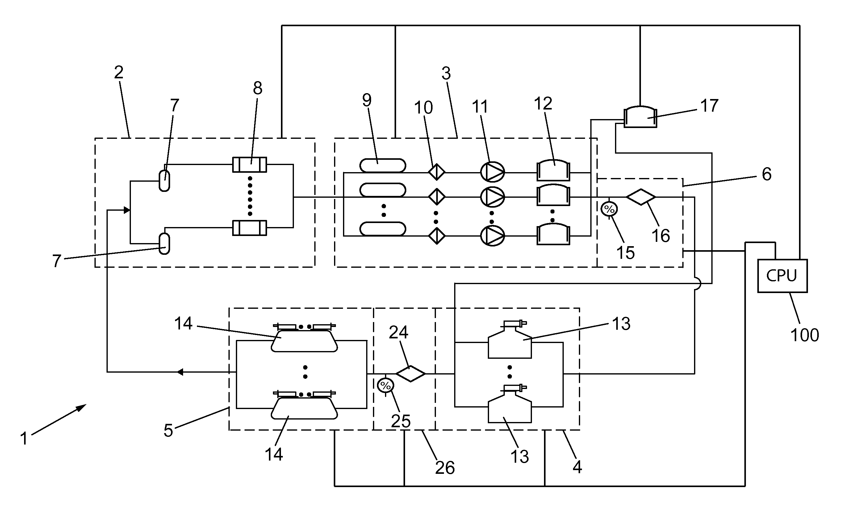
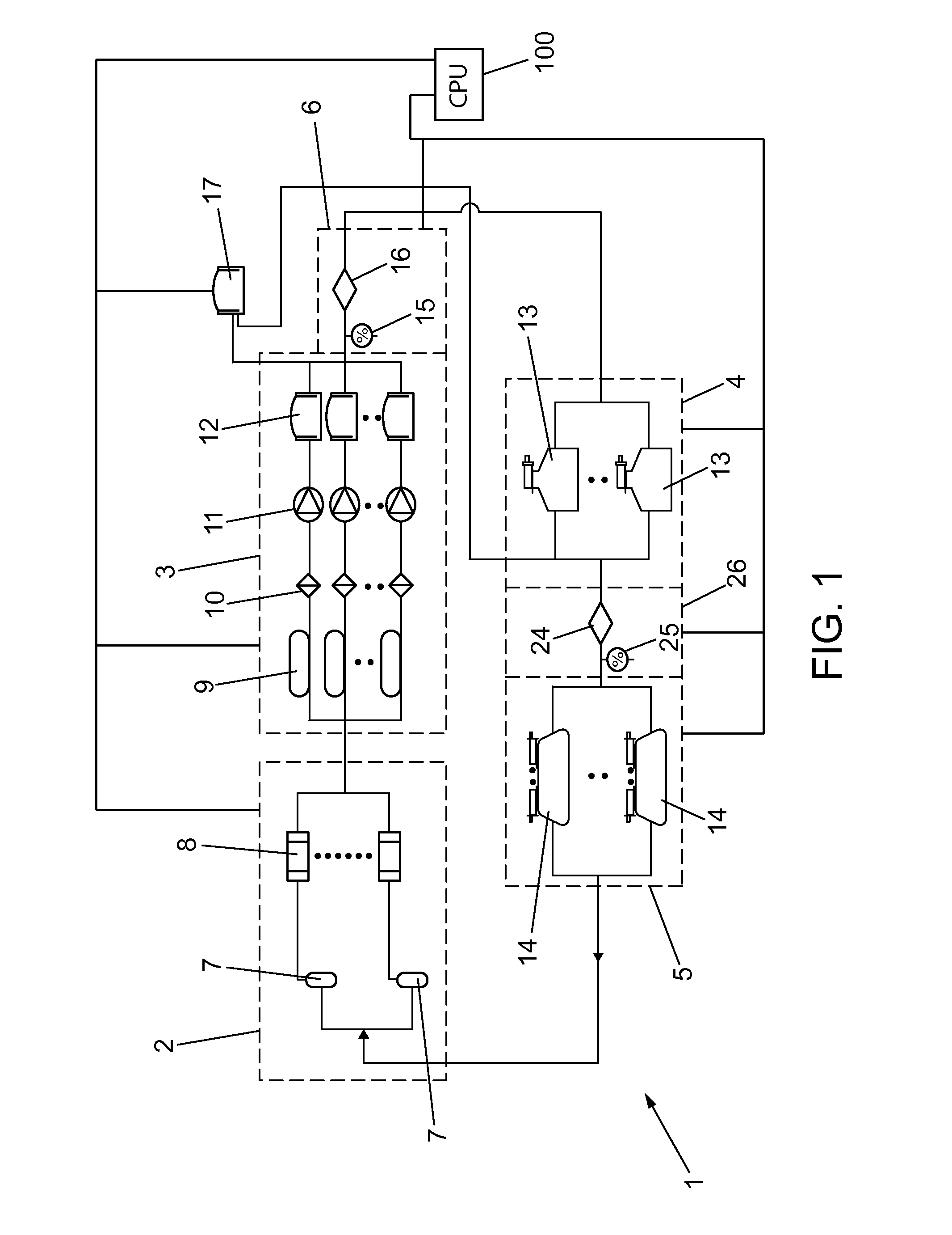
The patent describes a high-efficiency helium recovery plant that can be controlled by computer and switch between a standby mode and a liquefaction mode. It can collect, re-liquefy, and redistribute recovered helium among multiple medical or scientific instruments. The plant has a continuous recycling of helium, reducing the cost of resupply. It has a liquefaction rate comparable to the prior art Class M plants and performance efficiency of at least 4 liters / day / kW, but with simplified operating and maintenance procedures. It minimizes the storage time lapse of the evaporated gas and the volume of stored gas prior to liquefaction, reducing impurities. It provides a reserve of liquefied helium for immediate use. It can be scaled by increasing the number of liquefaction units and is scalable at higher available power of closed-cycle refrigerators.

Problems solved by technology

Although helium (He) is the second most abundant element in the universe, on earth it is scarce and only extracted with difficulty.
Furthermore, even where the loss is very small at one or more stages, when aggregated together the total loss can be significant and often exceeds 10% per cycle.
Furthermore, these plants require complex facilities for the storage of vast volumes of highly pressurized gas, regardless of the liquid consumption rate at the particular facility, since the liquefaction rate generally cannot be coordinated, regulated, or adapted for consumption.
Finally, without capability to adjust the liquefaction rate, the liquefied helium is produced in volumes that exceed consumption, which necessitates the use of very large storage Dewars, and consequently requires smaller transportation Dewars to distribute the liquid to end users of the liquid gas.
However, at present there has yet to be developed such a helium recovery plant based on GM or Pulse Tube technologies which is adapted to yield liquefaction efficiencies comparable to the class XL liquefaction plants described above; that is, one liter / hour / kW.
However, these systems are constructed to use one refrigerator per instrument, and thus underutilize the refrigerator's capacity.
For installations in which the direct installation of a refrigerator is technically not feasible, these closed-cycle refrigerator systems do not solve the problem of providing helium as and when required.
Moreover, when a large number of instruments require refrigeration, the acquisition and maintenance costs associated with the corresponding number of refrigerators make this solution impractical.

Method used


Image

  • Helium-recovery plant
  • Helium-recovery plant

Examples


Embodiment Construction

[0014]A closed-cycle, high-efficiency, automated helium recovery plant is here described. This high-efficiency helium recovery plant is adapted for computerized control and switching between a liquefaction mode and a standby mode, and is further adapted to collect, re-liquefy, and redistribute recovered helium amongst a plurality of medical or scientific instruments or other equipment. As helium gas is utilized among several instruments within the closed system, it is recovered and subsequently liquefied before being re-introduced to the equipment such that a finite supply of helium is continuously recycled, without or at least with only minimal loss, within the closed system, thus reducing the cost associated with resupply of virgin helium gas.

[0015]The helium recovery plant disclosed herein covers a liquefaction range of between zero liters / hour when operated in standby mode, and more than 10 liters / hour when operating in liquefaction mode, In this regard, this helium recovery pla...


PUM


Abstract

A helium recovery plant adapted to filter, compress, and purify helium gas collected from one or more helium-using instruments, as well as to liquefy and redistribute the purified gas within a closed system. The recovery plant is adapted to match the purification and liquefaction rate of the system with the consumption rate of the coupled instruments. Additionally, the recovery plant is adapted to match the liquefaction rate of a liquefaction module with a boil-off rate of liquid helium within a Dewar thereof. The recovery plant is further adapted to recycle helium therein in an effort to achieve zero loss.

Description

CROSS-REFERENCE TO RELATED APPLICATIONS[0001]This application claims priority from PCT serial number PCT / ES2010 / 070632, filed 28 Sep. 2010 with priority from Spanish application Serial No.: P200930904, filed 26 Oct. 2009, the contents of both of which are hereby incorporated by reference.BACKGROUND OF THE INVENTION[0002]1. Field of the Invention[0003]This concept relates generally to gas recovery plants, otherwise known as “gas liquefaction plants,” and more particularly to a modular gas recovery plant adapted for efficient gas supply, recovery, and storage in an effort to achieve zero helium loss within a closed system.[0004]2. Discussion of Related Art[0005]Although helium (He) is the second most abundant element in the universe, on earth it is scarce and only extracted with difficulty. Helium is found underground, in a gaseous state, as a byproduct of natural radioactive disintegrations. Separation methods are used to isolate helium from other gases found in natural gas wells.[00...

Claims


Application Information

Patent Timeline
Patent Type & Authority Applications(United States)
IPC IPC(8): F25J1/00F25J3/08
CPCF25J1/0065F25J1/025F25J2270/912F25J2290/60F25J2290/62F25J1/0276F25J3/08F25J1/0007F25J2220/02F25J1/0269F25J1/0225F25J1/027F25J1/0271F25J2270/908F25J1/02F25J3/029
Inventor RILLO MILL N, CONRADOTOCADO MART NEZ, LETICIA
Owner CONSEJO SUPERIOR DE INVESTIGACIONES CIENTIFICAS (CSIC)
Learn More