
Data Signal Threshold Detection and/or Recovery in Optical and/or Optoelectronic Receivers and/or Transceivers

a data signal and threshold detection technology, applied in the field of optical and/or optoelectronic receivers and/or transceivers, can solve the problems of inability to accurately detect the second packet, inability to process such high-bandwidth data signals sufficiently quickly, and inability of rc circuitry to process certain data signals having different amplitudes. to achieve the effect of fast and accurate data signal detection

Active Publication Date: 2013-05-02
SOURCE PHOTONICS
View PDF5 Cites 14 Cited by
  • Summary
  • Abstract
  • Description
  • Claims
  • Application Information

AI Technical Summary

Benefits of technology

The present detection circuit helps to quickly and accurately detect data signals in optical and optoelectronic receivers. It can determine the voltage level of the received signal and set a decision threshold for detecting different binary logic states. This allows the receiver to make quick and efficient decisions about the received data. The "feed-forward" circuitry helps to determine the decision threshold quickly, within 10 nanoseconds of the beginning of a new data packet. Overall, this detection circuit improves the speed and accuracy of data transfer in optical receivers.

Problems solved by technology

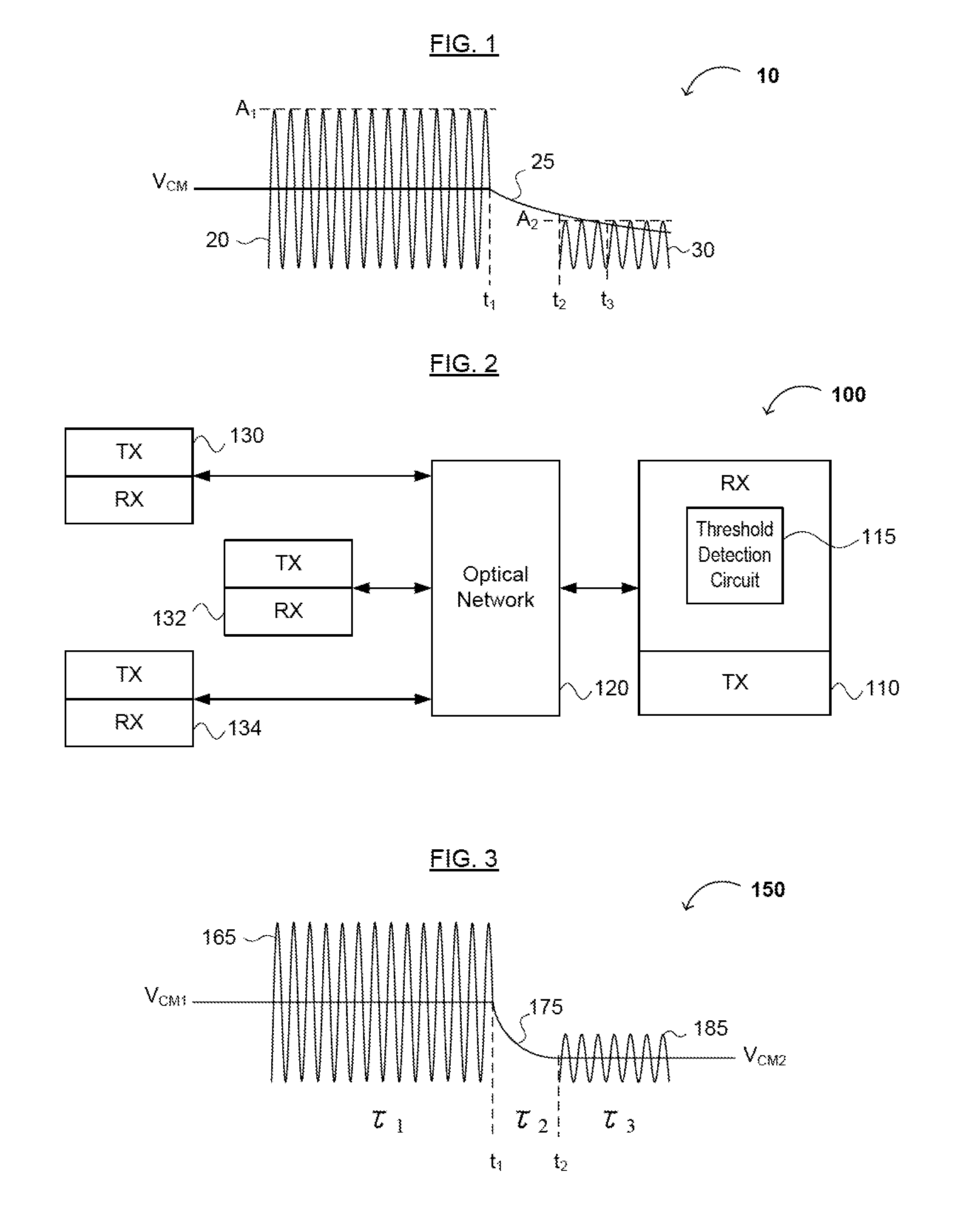
Thus, use of a common-mode voltage (e.g., VCM) established for the first packet may result in inaccurate reception of the second packet, since the amplitudes of the received packets are not necessarily equal (e.g., A2 may be significantly less than A1).
Such RC circuitry may not be capable of processing certain data signals having different amplitudes sufficiently quickly.
However, current optical receivers employing feedback configurations to determine an optical data signal decision threshold may not be capable of processing such high bandwidth data signals sufficiently quickly.
Such a configuration, however, increases data processing time, and data at the beginning of the data packet can be erroneously processed (e.g., treated as all binary logic “0”s) during the time that the decision threshold is being determined.

Method used


Image

  • Data Signal Threshold Detection and/or Recovery in Optical and/or Optoelectronic Receivers and/or Transceivers
  • Data Signal Threshold Detection and/or Recovery in Optical and/or Optoelectronic Receivers and/or Transceivers
  • Data Signal Threshold Detection and/or Recovery in Optical and/or Optoelectronic Receivers and/or Transceivers

Examples


Embodiment Construction

[0025]Reference will now be made in detail to various embodiments of the invention, examples of which are illustrated in the accompanying drawings. While the invention will be described in conjunction with the following embodiments, it will be understood that the descriptions are not intended to limit the invention to these embodiments. On the contrary, the invention is intended to cover alternatives, modifications and equivalents that may be included within the spirit and scope of the invention as defined by the appended claims. Furthermore, in the following detailed description, numerous specific details are set forth in order to provide a thorough understanding of the present invention. However, it will be readily apparent to one skilled in the art that the present invention may be practiced without these specific details. In other instances, well-known methods, procedures, components, and circuits have not been described in detail so as not to unnecessarily obscure aspects of th...


PUM


Abstract

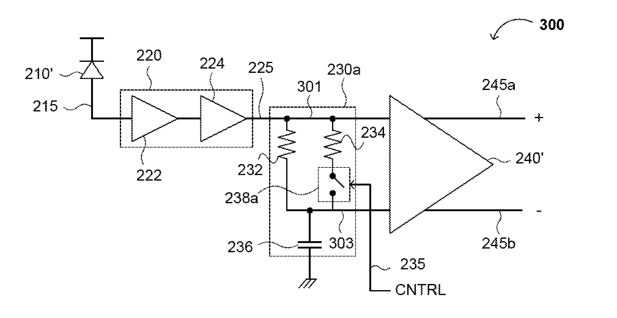
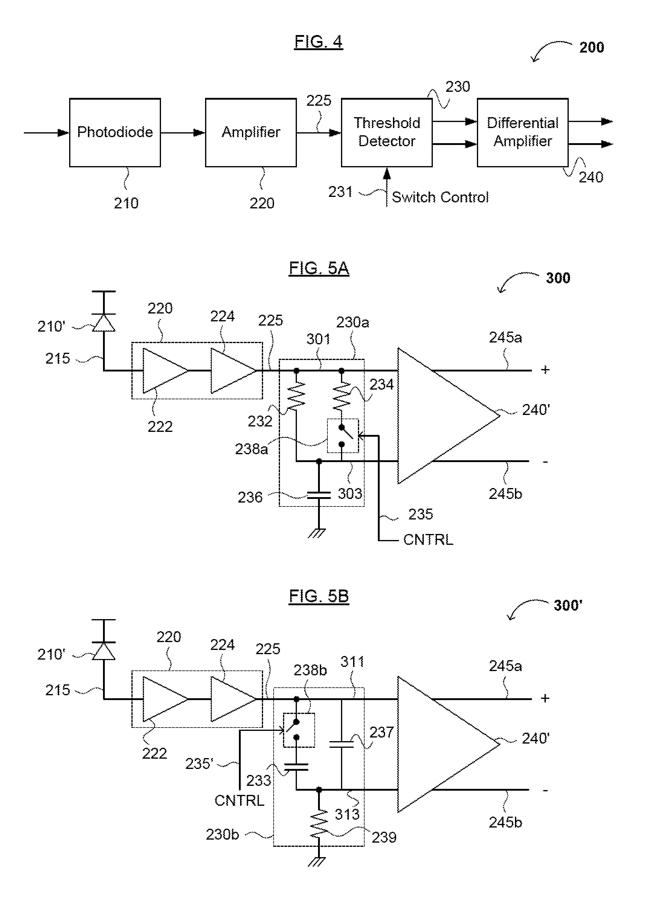
Methods for receiving a signal and a detection circuit are disclosed. The detection circuit and related methods may be useful for the fast and accurate receiving of data signals. The detection circuit generally comprises a first circuit having a first time constant, a second circuit having (i) a common input with the first circuit and (ii) a second time constant, the second time constant being less than the first time constant, and a switch configured to (i) charge the first circuit with an input signal when the switch is in a first state, and (ii) charge or discharge the second circuit with the input signal when the switch is in a second state, the switch having the second state when the input signal is no longer received at the common input.

Description

FIELD OF THE INVENTION[0001]The present invention generally relates to optical signal reception. More specifically, embodiments of the present invention pertain to methods and apparatuses for receiving optical signals using an optical and / or optoelectronic receiver and / or transceiver, wherein the optical signals may have different common-mode voltages.DISCUSSION OF THE BACKGROUND[0002]Passive optical networks (PONs) can be utilized to provide data from one or more user nodes (e.g., an optical network unit [ONU], optical network terminal [ONT], etc.) to a central node (e.g., a central office, such as or including an optical line terminal [OLT]) using optical signal media (e.g., a fiber optic cable, a fiber optic link, etc.). In some PONs, time-division multiplexing (TDM) is used so that multiple bit streams or data signals (e.g., data packets) are alternately transmitted by one or more ONUs over a single communication channel. That is, in PONs employing TDM, a first ONU can transmit ...

Claims


Application Information

Patent Timeline
Patent Type & Authority Applications(United States)
IPC IPC(8): H04B10/06G05F1/10
CPCH04B10/695
Inventor AZADEH, MOHAMMADMARGALIT, NEAR
Owner SOURCE PHOTONICS
Learn More