Energy storage device and method for the reversible storage of energy

a technology of energy storage and energy storage, which is applied in the direction of energy input, electrochemical generator, instruments, etc., can solve the problems of insufficient storage of electrical energy, inability to plan for the availability of electrical energy, and fluctuation of electrical energy generation, etc., and achieves the effect of simple and inexpensive manufacturing

Inactive Publication Date: 2013-05-09
SIEMENS AG
View PDF2 Cites 7 Cited by
  • Summary
  • Abstract
  • Description
  • Claims
  • Application Information

AI Technical Summary

Benefits of technology

[0006]An object is to provide an energy storage device for the reversible storage of energy which eliminates the above mentioned disadvantages, in particular is more efficient and at the same time can be manufactured simply and inexpensively.

Problems solved by technology

As the generation of electrical energy from renewable sources is subject to weather conditions such as cloud cover or wind strength, the generation of electrical energy fluctuates and it is much more difficult to plan for the availability of the electrical energy.
Hitherto electrical energy from renewable energy sources, because of their relatively low output, has generally been fed directly into the grid and in some cases conventional power plants have been derated accordingly, making it unnecessary to store the electrical energy from renewable energy sources.
However, electrolyzers of this kind are relatively inefficient.
In addition, much energy is required for compressing the hydrogen produced during electrolysis if water is electrolyzed into its constituent elements.

Method used


Image

  • Energy storage device and method for the reversible storage of energy
  • Energy storage device and method for the reversible storage of energy
  • Energy storage device and method for the reversible storage of energy

Examples


first embodiment

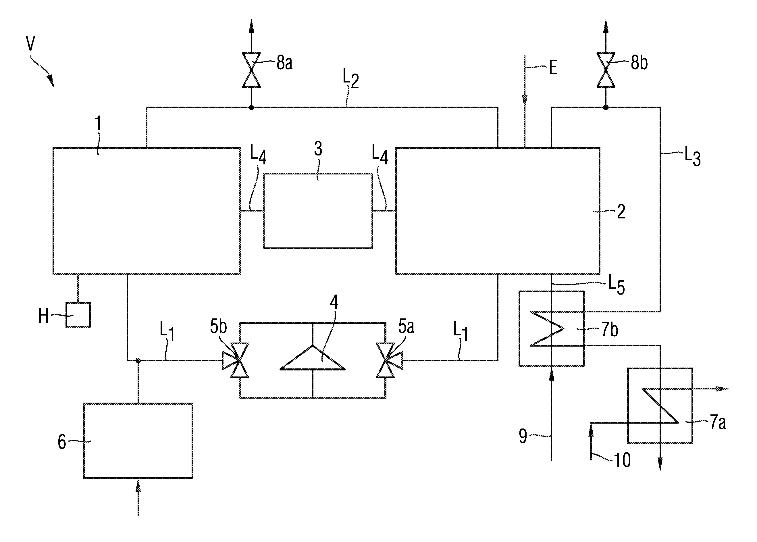
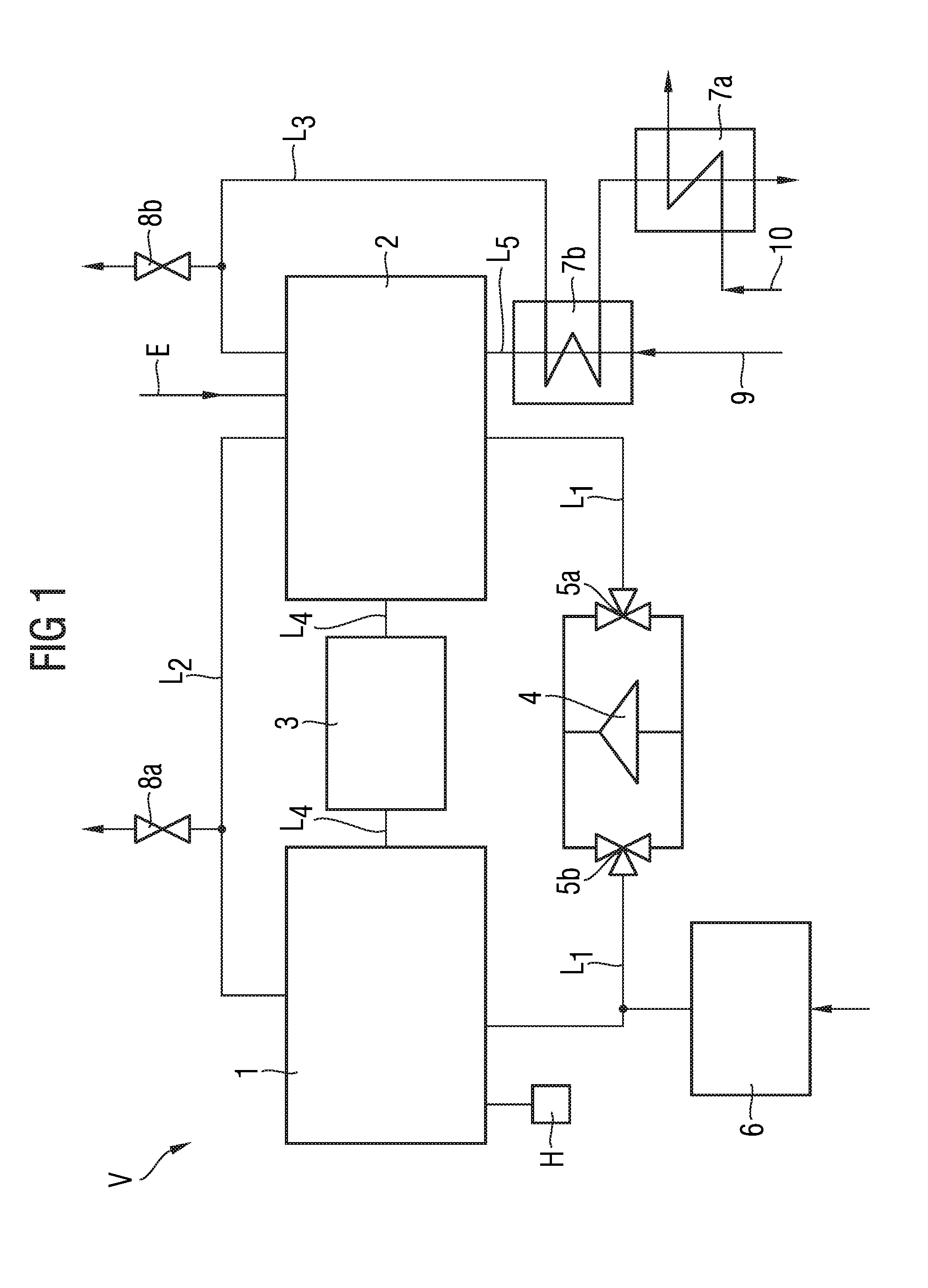
[0024]FIG. 1 schematically illustrates a design of an energy storage device according to the present invention.

[0025]In FIG. 1, reference character V denotes an energy storage device V according to the first embodiment of the present invention. It comprises a metal / metal oxide store 1 and a solid oxide electrolysis device 2 which are interconnected via lines L1, L2 for exchanging fluids, here water vapor and gaseous hydrogen respectively. Additionally disposed in the line L1 are a high-temperature blower 4 and three-way valves 5a, 5b downstream and upstream respectively of the high-temperature blower 4. The high-temperature blower 4 and the three-way valves 5a, 5b are used to control the direction of the fluid flowing through the lines L1 and L2 from the metal / metal oxide store 1 to the solid oxide electrolysis device 2 and vice versa.

[0026]An extraction valve 8a is disposed on the line L2 in order to be able to extract hydrogen gas and / or water vapor. In addition to the fluidic cou...

second embodiment

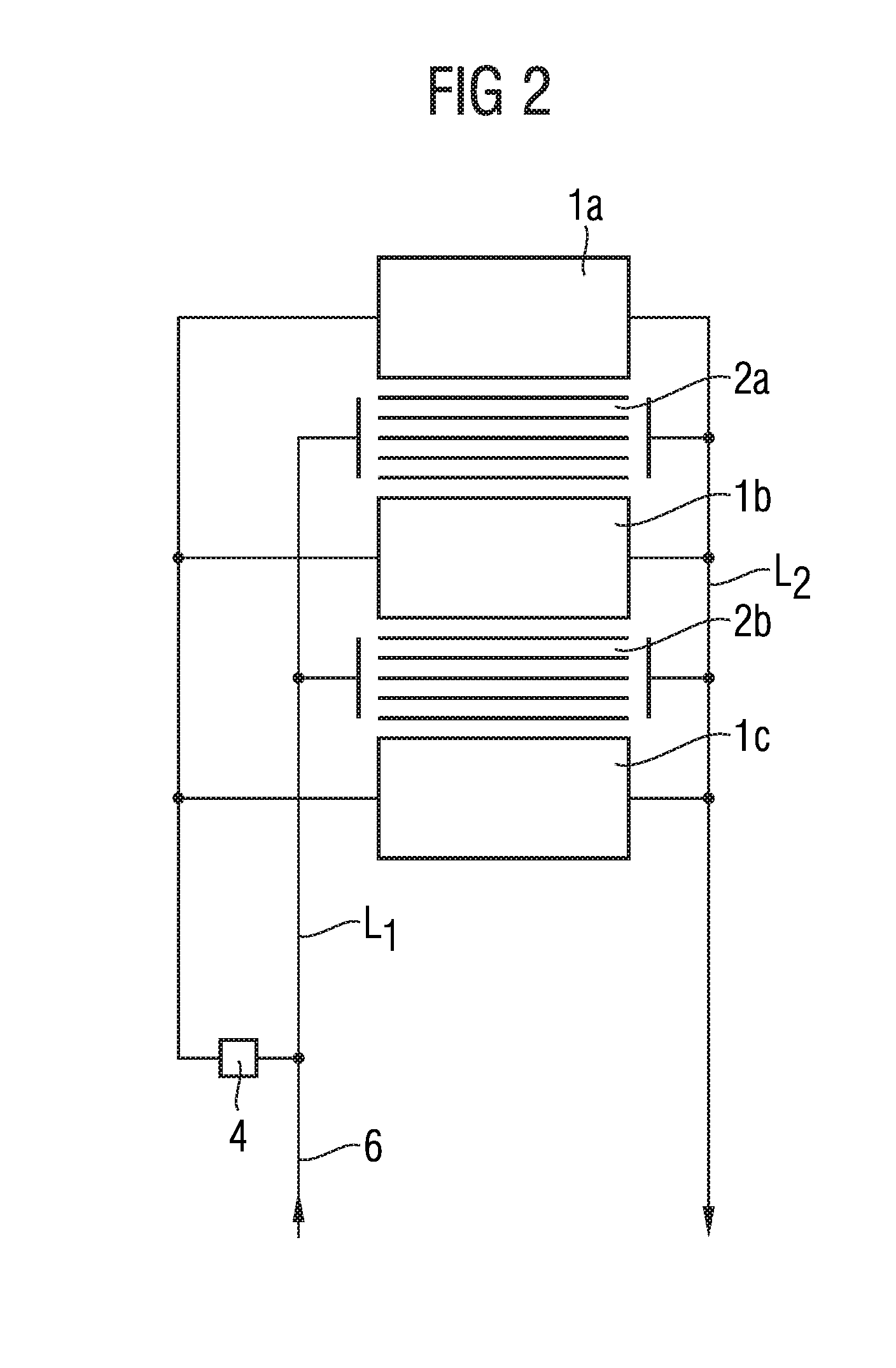
[0034]FIG. 2 shows an energy storage device according to the present invention. Schematically illustrated in FIG. 2 is an energy storage device V comprising a plurality of iron / iron oxide stores 1a, 1b, 1c and a plurality of solid oxide electrolysis devices 2a, 2b. These are disposed directly adjacent and alternately. The heat exchange between the iron / iron oxide stores 1a, 1b, 1c and the solid oxide electrolysis devices 2a, 2b takes place by means of convection, thermal conduction and / or radiation. The solid oxide electrolysis devices 2a, 2b are interconnected via a common line L1. Similarly to FIG. 1, water vapor is then fed via the lines L1 to the solid oxide electrolysis devices 2a, 2b which decompose the water vapor or water into hydrogen and oxygen. The hydrogen produced by the solid oxide electrolysis devices 2a, 2b is fed from the solid oxide electrolysis devices 2a, 2b via a common line L2 to the iron / iron oxide stores 1a, 1b, 1c where the hydrogen can be stored in the iron...


PUM

PropertyMeasurementUnit
operating temperatureaaaaaaaaaa

Abstract

An energy storage device for a reversible storage of energy has a reversibly designed metal/metal oxide storage unit for indirectly storing energy in form of a fluid material and a reversibly designed electrolysis device for providing and using the fluid material in an electrolysis reaction. The metal/metal oxide storage unit is disposed spatially separated from the electrolysis device. A fluid exchanging unit is provided for exchanging the fluid material between the reversibly designed metal/metal oxide storage unit and the electrolysis device, and a heat exchanging unit is provided for exchanging thermal energy between the metal/metal oxide storage unit and the electrolysis device. Further, a method for a reversible storage of energy is provided.

Description

CROSS REFERENCE TO RELATED APPLICATIONS[0001]This application is the US National Stage of International Application No. PCT / EP2011 / 058136 filed May 19, 2011, and claims the benefit thereof. The International Application claims the benefits of German Patent Application No. 20 2010 027 690.1 DE filed Jul. 20, 2010. All of the applications are incorporated by reference herein in their entirety.FIELD OF INVENTION[0002]The invention relates to an energy storage device for reversibly storing energy, in particular from renewable energy sources, and to a corresponding method.BACKGROUND OF INVENTION[0003]As a result of the ever increasing use of energy from renewable energy sources, e.g. from wind energy or solar energy, it is necessary to have means of storing the increasingly large amounts of energy produced thereby. As the generation of electrical energy from renewable sources is subject to weather conditions such as cloud cover or wind strength, the generation of electrical energy fluctu...

Claims


Application Information

Patent Timeline
Patent Type & Authority Applications(United States)
IPC IPC(8): H01M8/18
CPCC25B1/04H01M8/04014H01M8/04029H01M8/04216H01M8/0606H01M8/0656F17C11/005H01M8/186H01M8/188H01M2008/1293Y02E60/366Y02E60/525Y02E60/528H01M8/184Y02E60/36Y02E60/50Y02P20/129Y02P20/133
Inventor ISE, MARTINLANDES, HARALD
Owner SIEMENS AG
Why Eureka
Try Eureka