Rotor of an asynchronous machine with retaining element

a technology of retaining element and asynchronous machines, which is applied in the direction of synchronous motors, cage rotors, stator/rotor bodies, etc., can solve the problems of material cracks or even fractures, existing solutions are either particularly costly to implement, and not entirely suitabl

Active Publication Date: 2013-05-09
SIEMENS AG
View PDF10 Cites 15 Cited by
  • Summary
  • Abstract
  • Description
  • Claims
  • Application Information

AI Technical Summary

Benefits of technology

[0012]The retaining element prevents any plastic deformation or a fracture of the squirrel-cage winding at the respective junction between rotor rod and cage ring when the squirrel-cage rotor experiences high centrifugal force stress during operation of the asynchronous machine. According to an advantageous feature of the present invention, the high sheer stress in the squirrel-cage rotor is directly suppressed at the point of connection between the rotor rods and the cage rings. The retaining element may be designed as a disk with a circumferential edge which holds the external part of the cage ring and a subregion of the rods. The disk, which may also be designed as in form of spokes to save weight, is positioned rotatably fixed on the shaft.
[0013]The retaining element thus has a disk-shaped basic structure which has a circumferential edge. This edge is designed to be cylindrical and / or conical. If the shell surface of the rotor is a different shape, e.g. polygonal, the embodiment of the retaining element, in other words of the disk and of the edge, is adapted to the geometric circumstances. If the edge is designed to be conical, it tapers axially toward the center of the rotor. Advantageously, the retaining element may be designed in one piece, i.e. the retaining element may be made from a single material and may advantageously be manufactured in a single work process.
[0014]According to another advantageous feature of the present invention, the squirrel-cage rotor the cage ring is prevented, at the vulnerable junction, from moving radially outward and possibly breaking off because of thermal expansion and / or stresses due to the centrifugal force. The retaining element may here be advantageously manufactured from a particularly high-tensile material, for example steel.
[0017]Since with this design the external diameter of the squirrel-cage rotor is turned to adjust the size of the air gap between rotor and stator, the additional machining in the region of the cage rings does not add significant extra costs.

Problems solved by technology

Additionally, as a result of high temperatures that cause a thermal expansion of, among other things, the cage ring, and of the high centrifugal forces mentioned, the material is subject to a great deal of stress at the junction between rod and cage ring, which ultimately can result in cracks or even fractures in the material.
The existing solutions are either particularly costly to implement, because they consist of a plurality of different parts, or they are not entirely suitable for the vulnerable junction between rotor rod and cage ring.

Method used


Image

  • Rotor of an asynchronous machine with retaining element
  • Rotor of an asynchronous machine with retaining element
  • Rotor of an asynchronous machine with retaining element

Examples


Embodiment Construction

[0027]Throughout all the figures, same or corresponding elements may generally be indicated by same reference numerals. These depicted embodiments are to be understood as illustrative of the invention and not as limiting in any way. It should also be understood that the figures are not necessarily to scale and that the embodiments are sometimes illustrated by graphic symbols, phantom lines, diagrammatic representations and fragmentary views. In certain instances, details which are not necessary for an understanding of the present invention or which render other details difficult to perceive may have been omitted.

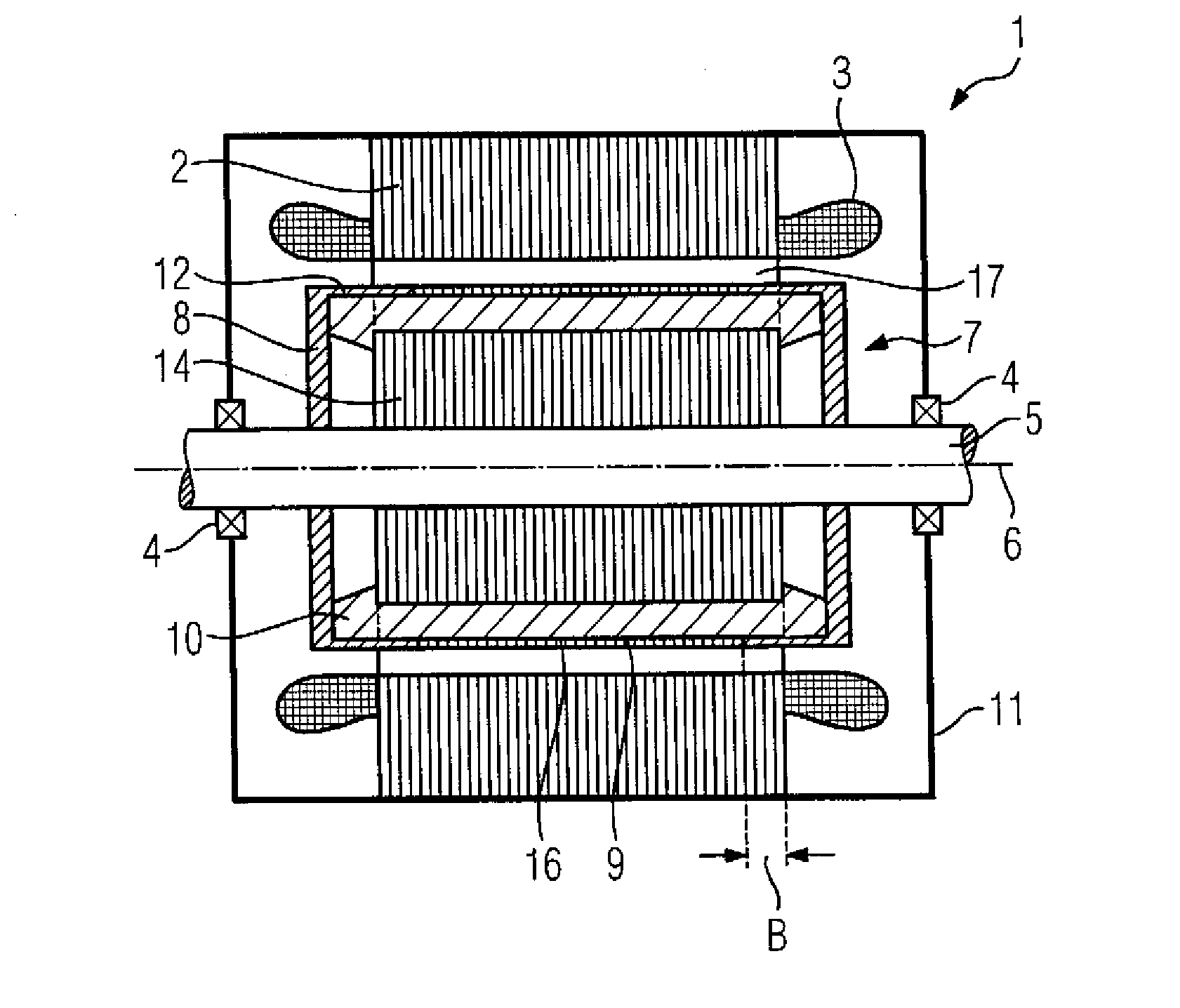
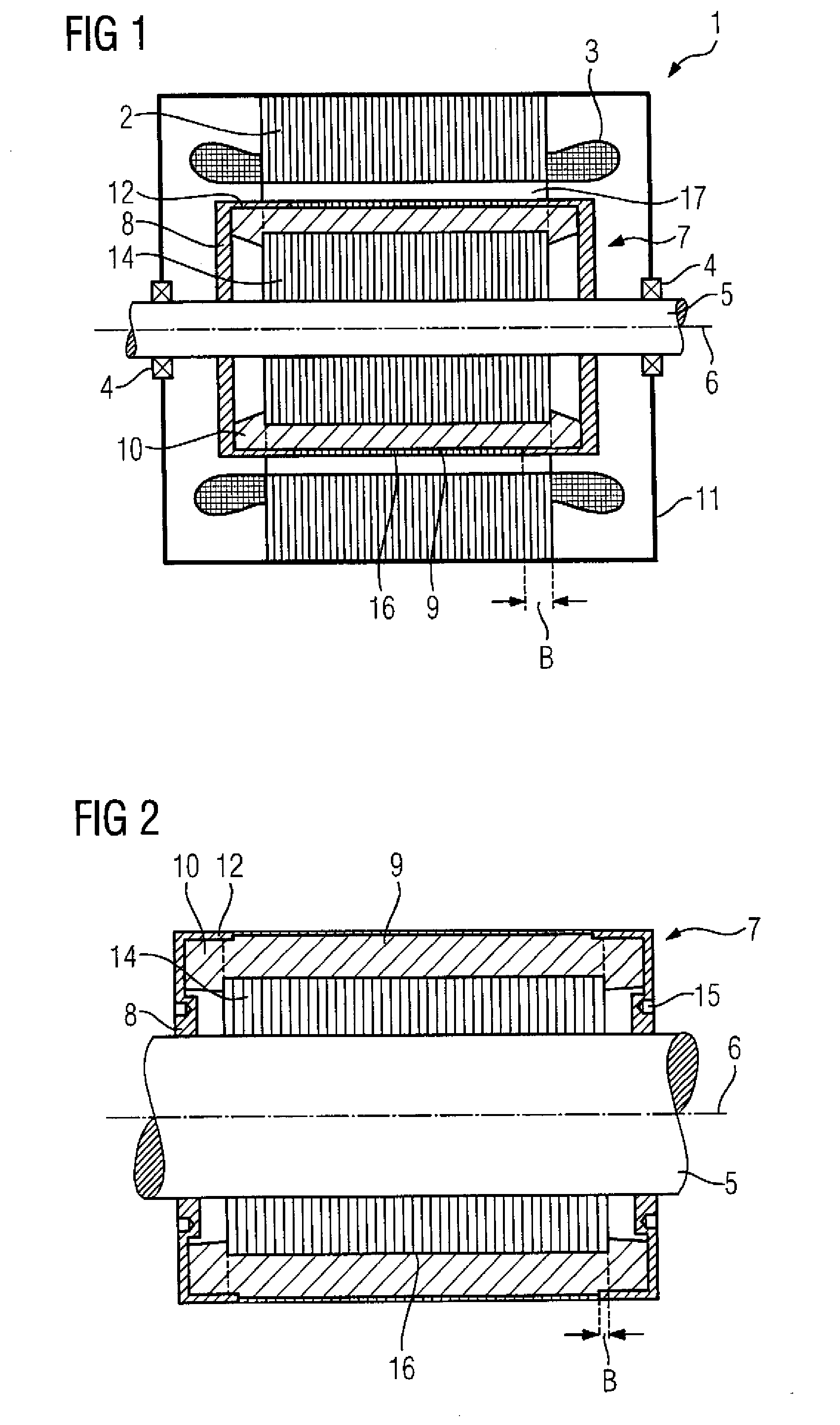
[0028]Turning now to the drawing, and in particular to FIG. 1, there is shown an asynchronous machine 1 in a housing 11 which has a stator 2 and a winding system (not shown in greater detail) which forms winding heads 3 on the end faces of the stator 2. Spaced apart from the stator 2 by an air gap 17 is the rotor 7. The rotor 7 is a squirrel-cage rotor which among other thin...


PUM

PropertyMeasurementUnit
rotation speedaaaaaaaaaa
diameteraaaaaaaaaa
strengthaaaaaaaaaa

Abstract

A squirrel-cage rotor of an asynchronous machine, in particular a die-cast rotor, includes a rotatable shaft, a laminated core being rotation-locked on the shaft and having grooves and opposing end faces. A squirrel-cage winding has rotor rods disposed in the grooves and a cage ring disposed on each of the end faces and electrically connecting the rotor rods. A pair of retaining elements is disposed on the shaft, wherein each retaining element extends in a radial direction in form of a disk or a spoke and has in an axial direction a wall and / or an axially extending finger. The wall overlaps on a radial periphery in the axial direction both the cage ring and a predefined axial section of the rotor rods that terminate in the cage ring, without increasing an external diameter of the laminated core.

Description

CROSS-REFERENCES TO RELATED APPLICATIONS[0001]This application claims the priority of European Patent Application, Serial No. EP 11 188 355.9 filed Nov. 9, 2011, pursuant to 35 U.S.C. 119(a)-(d), the content of which is incorporated herein by reference in its entirety as if fully set forth herein.BACKGROUND OF THE INVENTION[0002]The present invention relates to a squirrel-cage rotor of an asynchronous machine, in particular a die-cast rotor. The invention also relates to an asynchronous machine with a rotor of this type and a method for manufacturing a rotor of this type.[0003]The following discussion of related art is provided to assist the reader in understanding the advantages of the invention, and is not to be construed as an admission that this related art is prior art to this invention.[0004]Asynchronous machines normally have a cage rotor or squirrel-cage rotor. For this purpose rods are for example positioned in axially running grooves of the laminated core of the rotor. On ...

Claims


Application Information

Patent Timeline
Patent Type & Authority Applications(United States)
IPC IPC(8): H02K17/16H02K15/00H02K15/06
CPCH02K17/165H02K15/06Y10T29/49012H02K15/165H02K15/0012
Inventor DOLZ, VOLKER
Owner SIEMENS AG
Why Eureka
Try Eureka