High solidity and low entrance angle impellers on turbine rotor disk

a technology of turbine rotor disk and impeller, which is applied in the direction of machines/engines, mechanical equipment, transportation and packaging, etc., can solve the problems of high efficiency and output of engine, low operating temperature of turbine engine, and very sensitive performance of gas turbine engin

Active Publication Date: 2013-05-09
RAYTHEON TECH CORP
View PDF7 Cites 13 Cited by
  • Summary
  • Abstract
  • Description
  • Claims
  • Application Information

AI Technical Summary

Problems solved by technology

Therefore on the one hand the turbine operating temperature, efficiency and output of the engine are limited by the high temperature capabilities of the various turbine elements and th...

Method used


Image

  • High solidity and low entrance angle impellers on turbine rotor disk
  • High solidity and low entrance angle impellers on turbine rotor disk
  • High solidity and low entrance angle impellers on turbine rotor disk

Examples


Embodiment Construction

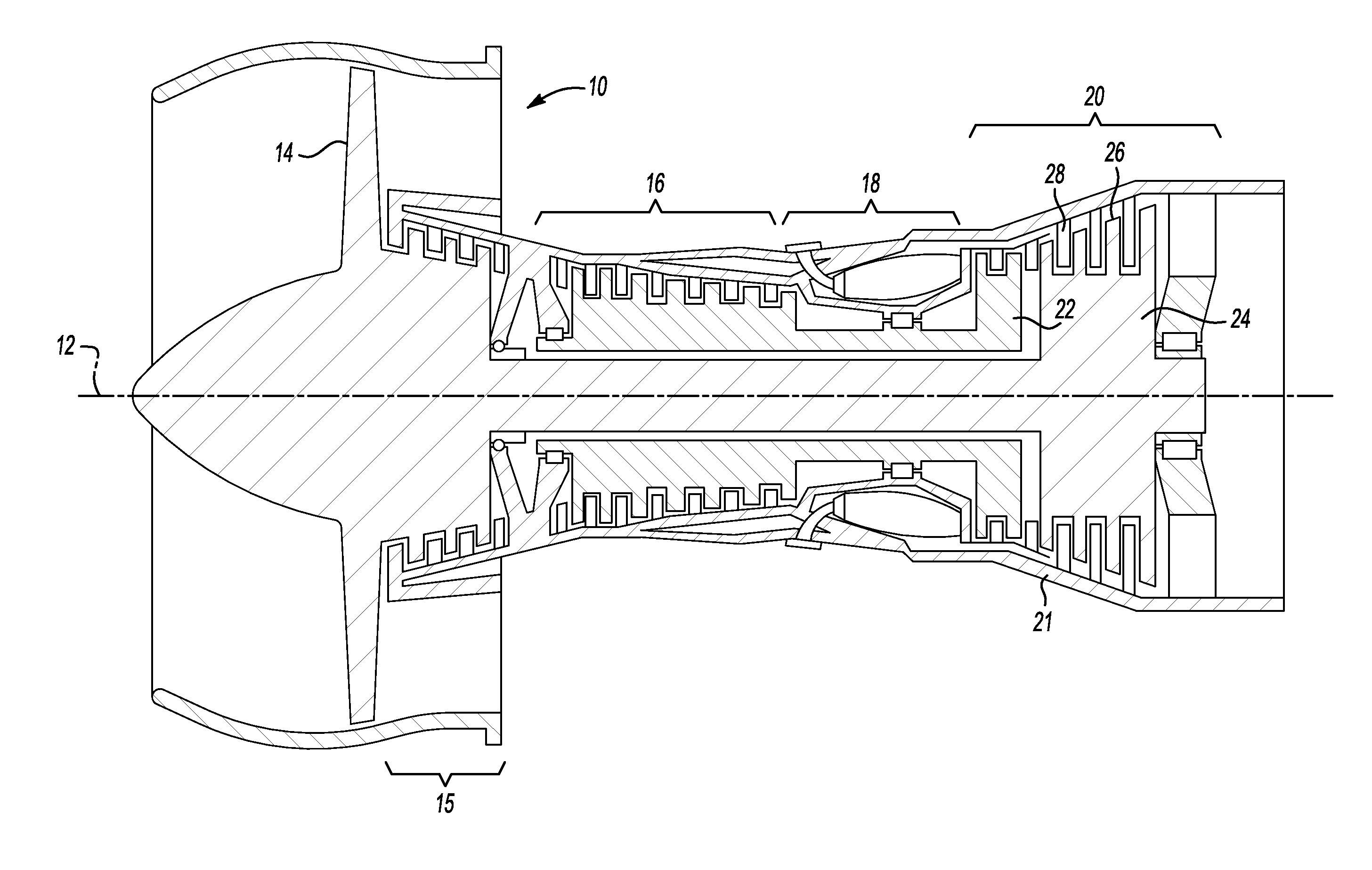
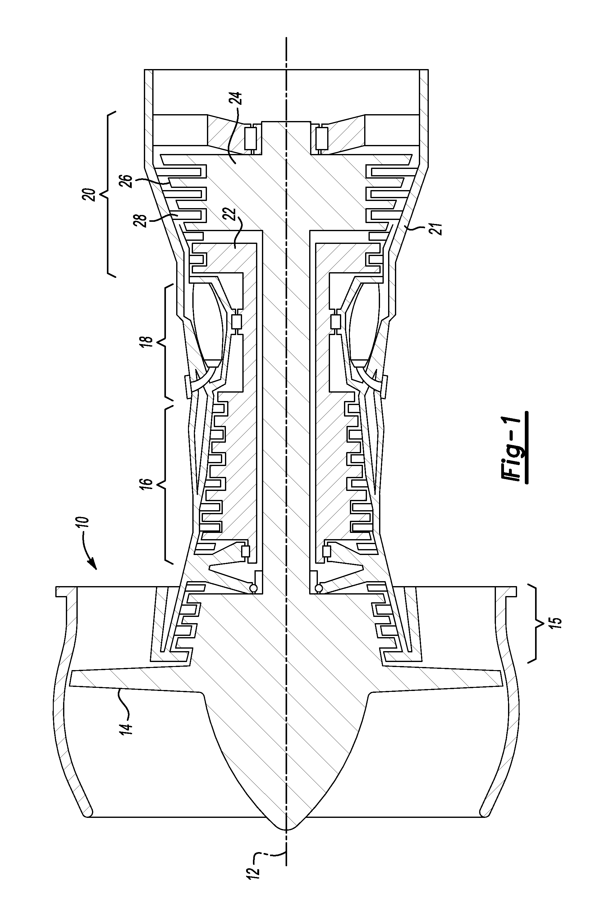
[0015]Referring to FIG. 1, a gas turbine engine 10, such as a turbofan gas turbine engine 10, circumferentially disposed about an engine centerline, or axial centerline axis 12, is shown. The engine 10 includes a case 21, a fan 14, compressor sections 15 and 16, a combustion section 18 and a turbine 20. As is well known in the art, air compressed in the compressor 15 / 16 is mixed with fuel and burned in the combustion section 18 and expanded in turbine 20. The turbine 20 includes high pressure and low pressure turbine rotors 22 and 24, which rotate in response to the expansion. The turbine 20 comprises alternating rows of rotary airfoils or blades 26 and static airfoils or vanes 28. It should be understood that this view is included simply to provide a basic understanding of the sections in a gas turbine engine, and not to limit the invention. For example, while a fan 14 is shown, this invention may be used in turbines that do not include a fan section.
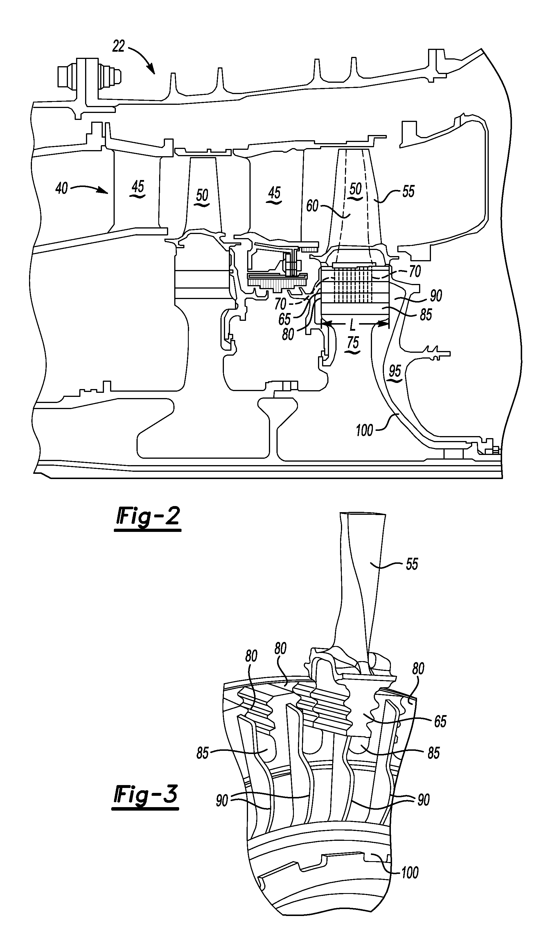
[0016]Referring now to FIGS. ...


PUM


Abstract

According to an embodiment disclosed herein, an apparatus for cooling a rotating part having cooling channels therein, the rotating part attaching to a disk rotating about an axis, the disk having a conduit for feeding a cooling fluid to the cooling channel is described. The apparatus has a first impeller rotating with the disk and in register with the conduit and an outer periphery of the disk, the impeller directing the cooling flow to the conduit.

Description

TECHNICAL FIELD[0001]The invention is applicable to a gas turbine engine cooling system and more particularly to an improved apparatus for supplying cooling fluid to hot parts of the engine, specifically, the interior of the turbine blade.BACKGROUND OF THE INVENTION[0002]It is widely recognized that the efficiency and energy output of a gas turbine engine can be improved by increasing the operating temperature of the turbine. Under elevated operating temperatures, gas turbine engine components such as the turbine rotors and blades are cooled by a flow of compressed air discharged at a relatively cool temperature. The flow of coolant across the turbine rotor and through the interior of the blades removes heat so as to prevent excessive reduction of the mechanical strength properties of the blades and rotor.[0003]Therefore on the one hand the turbine operating temperature, efficiency and output of the engine are limited by the high temperature capabilities of the various turbine eleme...

Claims


Application Information

Patent Timeline
IPC IPC(8): F01D5/18
CPCF01D5/082F01D5/3007F01D5/187F05D2250/713F05D2250/75
Inventor WU, CHARLES C.MCCUSKER, KEVIN N.
Owner RAYTHEON TECH CORP
Why Eureka
Try Eureka