Rotating airfoil component of a turbomachine

a technology of rotating airfoil and turbomachine, which is applied in the direction of liquid fuel engines, vessel construction, marine propulsion, etc., can solve the problems that the airfoil of gas turbine buckets and nozzles often requires complex cooling schemes, and achieves the reduction of cooling air flow, increased operating temperatures, and fatigue life.

Active Publication Date: 2013-05-09
GENERAL ELECTRIC CO
View PDF6 Cites 18 Cited by
  • Summary
  • Abstract
  • Description
  • Claims
  • Application Information

AI Technical Summary

Benefits of technology

[0007]A technical effect of the invention is the ability to thermally protect an angel wing so that its creep and fatigue life requirements can be met, while allowing for higher operating temperatures within a turbomachine and / or a reduction in cooling air flow used to protect the angel wings.
[0008]Other aspects and advantages of this invention will be better appreciated from the following detailed description.

Problems solved by technology

For this reason, airfoils of gas turbine buckets and nozzles often require complex cooling schemes in which air is forced through internal cooling passages within the airfoil and then discharged through cooling holes at the airfoil surface.

Method used


Image

  • Rotating airfoil component of a turbomachine
  • Rotating airfoil component of a turbomachine
  • Rotating airfoil component of a turbomachine

Examples


Embodiment Construction

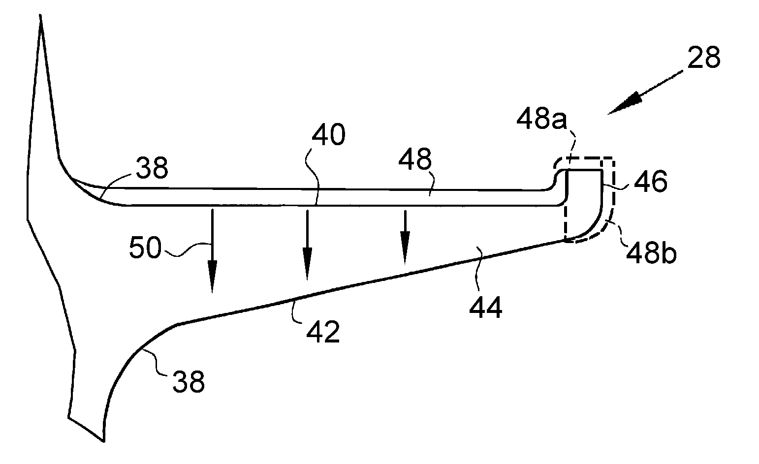
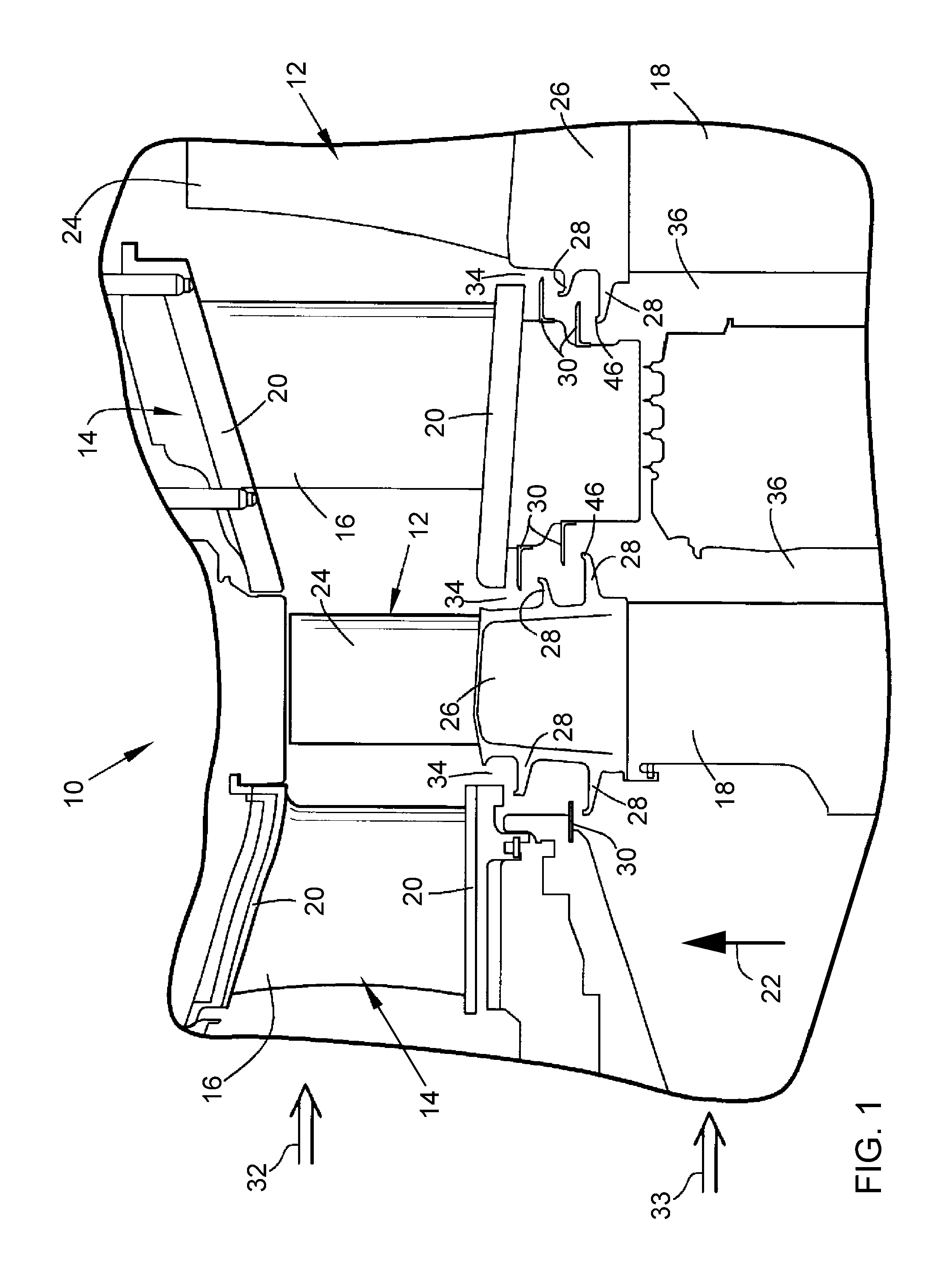
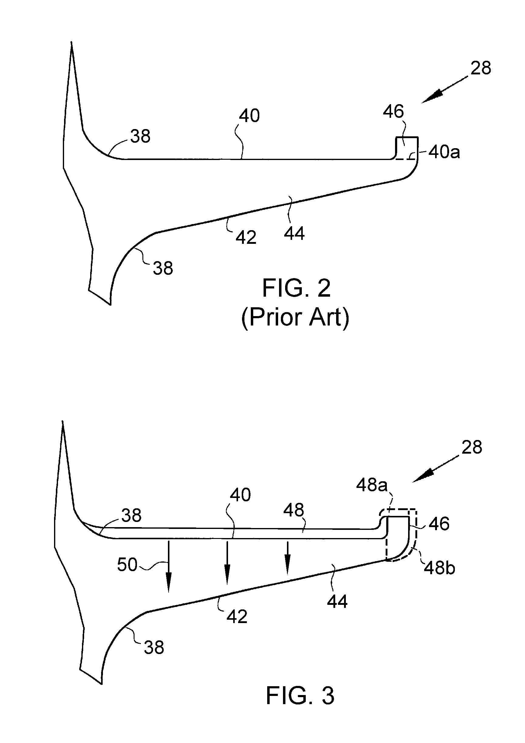
[0012]The invention will be described in reference to the turbine section 10 schematically represented in FIG. 1. The previous discussion of FIG. 1 is therefore applicable to the following discussion, which will focus primarily on aspects of the invention that differ from what was previously described in reference to FIG. 1. However, it should be understood that the invention is not limited to the turbine section 10 and its particular configuration represented in FIG. 1. In particular, the invention is not limited to the particular buckets 12 represented in FIG. 1, but is more generally applicable to rotating airfoil components of turbomachines, including but not limited to gas turbines, land-based gas turbine engines, aircraft gas turbine engines, and steam turbines. Furthermore, the invention is not limited to the particular configurations and numbers of the angel wings 28 and lands 30 represented in FIG. 1.

[0013]The buckets 12 and components of the nozzle assembly 14 shown in FIG...


PUM


Abstract

A rotating airfoil component equipped with one or more angel wings that inhibit the ingress of a hot working fluid into interior regions of a turbomachine in which the component is installed. The component includes an airfoil and a feature for mounting the component to enable rotation of the component within the turbomachine. An angel wing projects from the component to have a first surface facing the airfoil, an oppositely-disposed second surface facing the mounting feature, and at least one lateral surface therebetween. A thermal-insulating coating system is present on the first surface to inhibit heat transfer from the working fluid to the angel wing but not on the second or lateral surfaces so as not to inhibit heat transfer from the second and lateral surfaces of the angel wing.

Description

BACKGROUND OF THE INVENTION[0001]The present invention generally relates to structures subject to high stresses and high temperatures, such as rotating components of gas turbines and other turbomachinery. More particularly, this invention relates to a method of inhibiting heat transfer to angel wings of turbine buckets (blades) so as to reduce the temperature of the angel wings and / or reduce the cooling requirements of the angel wings.[0002]Buckets (blades), nozzles (vanes), and other components located in the hot gas path within turbine sections of gas turbines are typically formed of nickel-, cobalt- or iron-base superalloys with desirable mechanical and environmental properties for turbine operating temperatures and conditions. Because the efficiency of a gas turbine is dependent on its operating temperatures, there is a demand for components that are capable of withstanding increasingly higher temperatures. As the maximum local temperature of a component approaches the melting t...

Claims


Application Information

Patent Timeline
Patent Type & Authority Applications(United States)
IPC IPC(8): F01D5/14
CPCF01D5/288Y02T50/671F01D11/02Y02T50/60
Inventor ITZEL, GARY MICHAELPENNY, CHRISTOPHER MICHAELSMITH, AARON EZEKIELBRUCE, KEVIN LEON
Owner GENERAL ELECTRIC CO
Why Eureka
Try Eureka