Thin film lithium-ion battery

Active Publication Date: 2013-05-09
WANG CHIA GEE
View PDF12 Cites 5 Cited by
  • Summary
  • Abstract
  • Description
  • Claims
  • Application Information

AI Technical Summary

Benefits of technology

[0006]The present invention is directed to a thin film lithium-ion battery having at least a laminate structure incorporating at least a structurally stable silic

Problems solved by technology

One main drawback of the Si-based anode is the notable volume change during the lithium in

Method used


Image

  • Thin film lithium-ion battery
  • Thin film lithium-ion battery
  • Thin film lithium-ion battery

Examples


Embodiment Construction

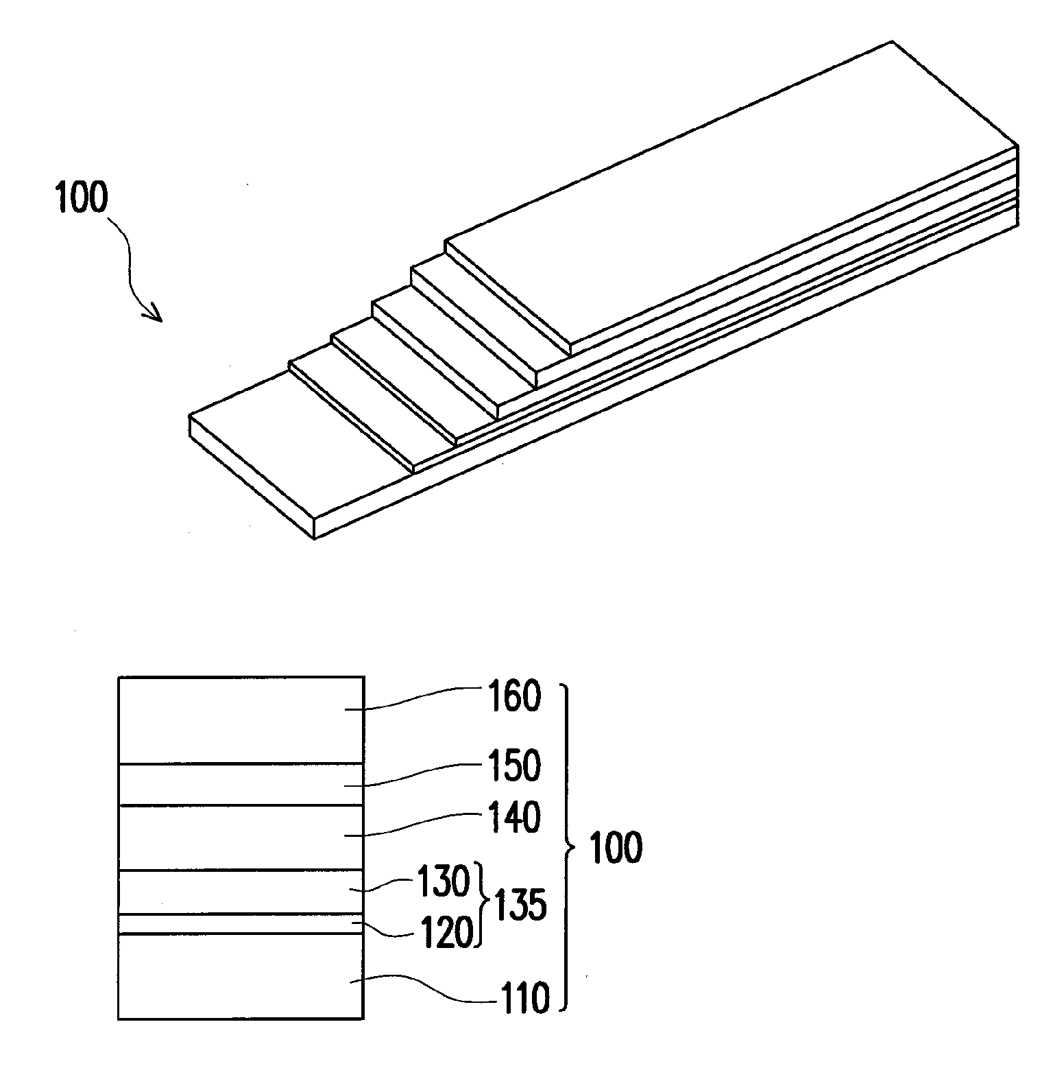
[0013]The present invention is directed to a thin film lithium-ion battery having at least a laminate structure incorporating at least a structurally stable silicon-based superlattice anode. Taking advantage of the silicon-based superlattice anode, the battery offers a large gravimetric capacity, a high cyclability and a high battery loading / charging capacity rate (i.e. C-rate).

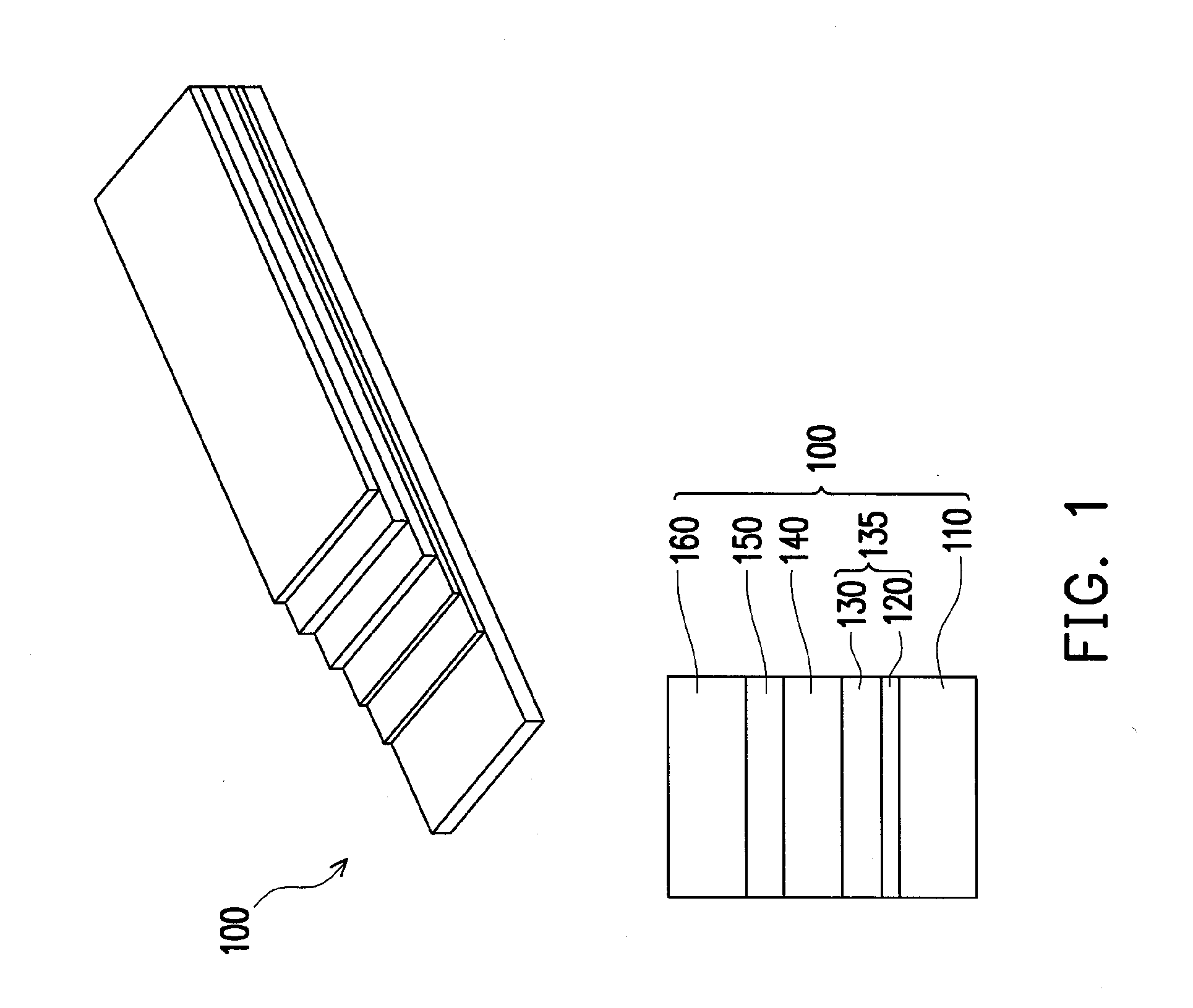
[0014]FIG. 1 is a schematic display of a laminate structure for the thin film battery according to an embodiment of this invention. The upper part of FIG. 1 shows a three-dimensional view of the laminate structure 100, while the lower part of FIG. 1 shows a schematic cross-sectional view of the laminate structure 100. The thin film battery includes at least a laminate structure 100 consisting of a bottom current collector layer 110, a superlattice layer 120, a silicon based layer 130, an electrolyte and separator (electrolyte / separator) 140, a cathode 150 and a top current collector layer 160, sequentially. T...


PUM


Abstract

The present invention is directed to a thin film lithium-ion battery having at least a laminate structure therein. The laminate structure includes a bottom current collector layer, an anode consisting of a superlattice layer and a silicon based layer, an electrolyte and separator, a cathode and a top current collector layer sequentially stacked together. The electrolyte and separator of the laminate structure contains lithium ions.

Description

CROSS-REFERENCE TO RELATED APPLICATION[0001]This application claims the priority benefits of U.S. provisional application Ser. No. 61 / 557,365, filed on Nov. 8, 2011 and Taiwan application serial no. 101141446, filed on Nov. 7, 2012. The entirety of each of the above-mentioned patent applications is hereby incorporated by reference herein and made a part of this specification.BACKGROUND OF THE INVENTION[0002]1. Field of the Invention[0003]The present invention generally relates to a battery. More particularly, the present invention relates to a thin film lithium-ion battery.[0004]2. Description of Related Art[0005]Lithium-ion batteries are one of the most popular types of the rechargeable battery for portable electronics. Following the development of the solid electrolyte that fulfils both functions of the electrolyte and the separator, the thin film lithium-ion batteries with a silicon-based anode and a carbon nanotube-based cathode have been put into practice. One main drawback of ...

Claims


Application Information

Patent Timeline
IPC IPC(8): H01M10/0525
CPCH01M10/0525H01M4/366H01M4/386Y02E60/122H01M10/0436H01M10/0562H01M10/0585H01M4/587Y02E60/10Y02P70/50
Inventor WANG, CHIA-GEE
Owner WANG CHIA GEE
Why Eureka
Try Eureka