
Detector, preamplifier selection apparatus, systems, and methods

a selection apparatus and preamplifier technology, applied in the field of detection and selection apparatus, can solve the problems of contaminating fluids, affecting the operation range, and invading fluid filtrates, so as to increase operational efficiency and client satisfaction, and accurately assess the composition of fluid samples.

Active Publication Date: 2013-05-16
HALLIBURTON ENERGY SERVICES INC
View PDF3 Cites 4 Cited by
  • Summary
  • Abstract
  • Description
  • Claims
  • Application Information

AI Technical Summary

Benefits of technology

The patent text describes a technique for evaluating the optical properties of fluids captured during drilling operations to determine their contamination level. The technique involves using optical detectors and amplifiers to measure the fluid's optical properties. The patent also discusses the challenges of obtaining a usable signal-to-noise ratio (SNR) due to the wide temperature range of downhole operations. The text proposes different combinations of optical detectors and amplifiers to overcome these challenges and provide better SNR for each combination. The technical effect of this patent is to provide a more reliable and accurate way of evaluating the contamination level of downhole fluids during drilling operations.

Problems solved by technology

However, during drilling operations, fluid filtrate invades the formation and tends to contaminate fluids near the well bore.
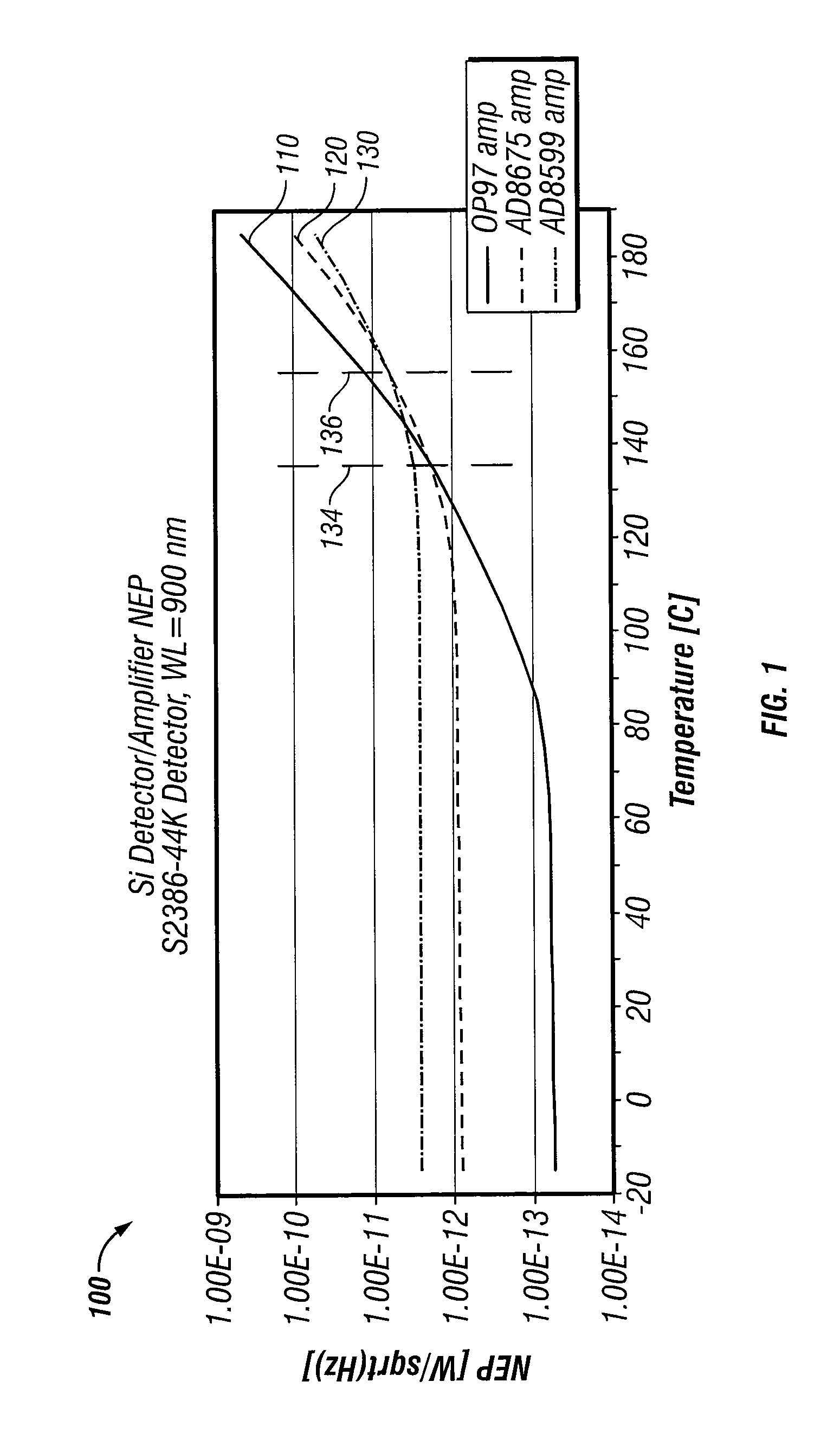
The wide temperature range of downhole operations poses some challenges with respect to obtaining a usable SNR.
Thus, amplifier selection for a silicon-based detector may result in sacrificing low temperature performance, with a better high temperature SNR.
Likewise, the same amplifier may not be the best choice when different detectors are used.
While a noise figure might be published for an amplifier, using a “low-noise” amplifier does not necessarily produce a combination of detector and amplifier that has a low NEP, given a particular set of environmental operating conditions.

Method used


Image

  • Detector, preamplifier selection apparatus, systems, and methods
  • Detector, preamplifier selection apparatus, systems, and methods
  • Detector, preamplifier selection apparatus, systems, and methods

Examples


Embodiment Construction

[0009]One technique that may be used to determine sampled fluid properties is that of evaluating the optical properties of the fluid sample. The optical properties of a fluid sample can in turn be used to determine the fluid's level of contamination, fluid type, fluid composition, and pressure, volume, temperature (PVT) properties. In some embodiments, the technique involves directing visible, near infra-red (IR), and mid-IR radiation through a fluid sample so that the properties of the radiation after passing through the fluid can be measured.

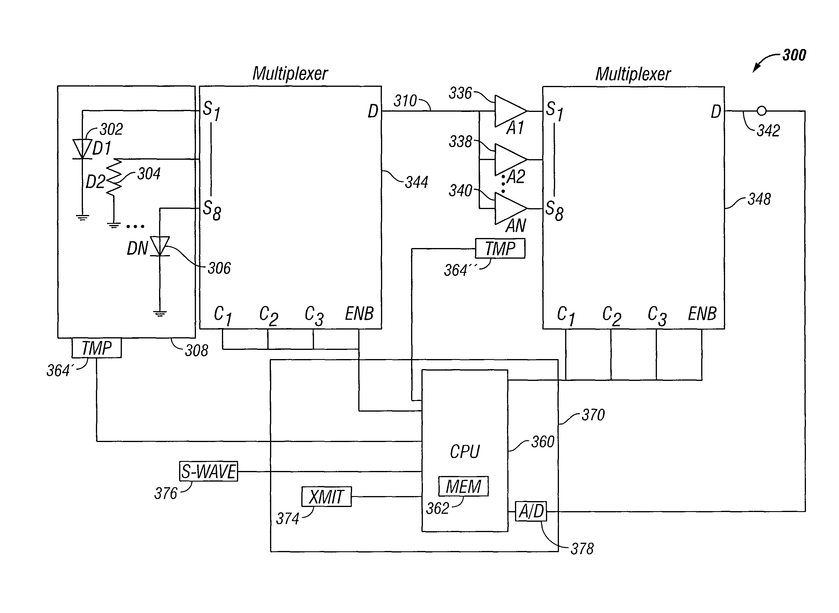
[0010]In many embodiments, the range of radiation wavelengths to be detected is from about 300 nm to about 5000 nm. To detect this radiation after it passes through a fluid sample, combinations of optical detectors and amplifiers (e.g., in the form of an instrumentation preamplifier) can be used. The elements of these apparatus are selected to provide an improved signal-to-noise ratio (SNR) when subjected to downhole operating conditions (e.g....


PUM


Abstract

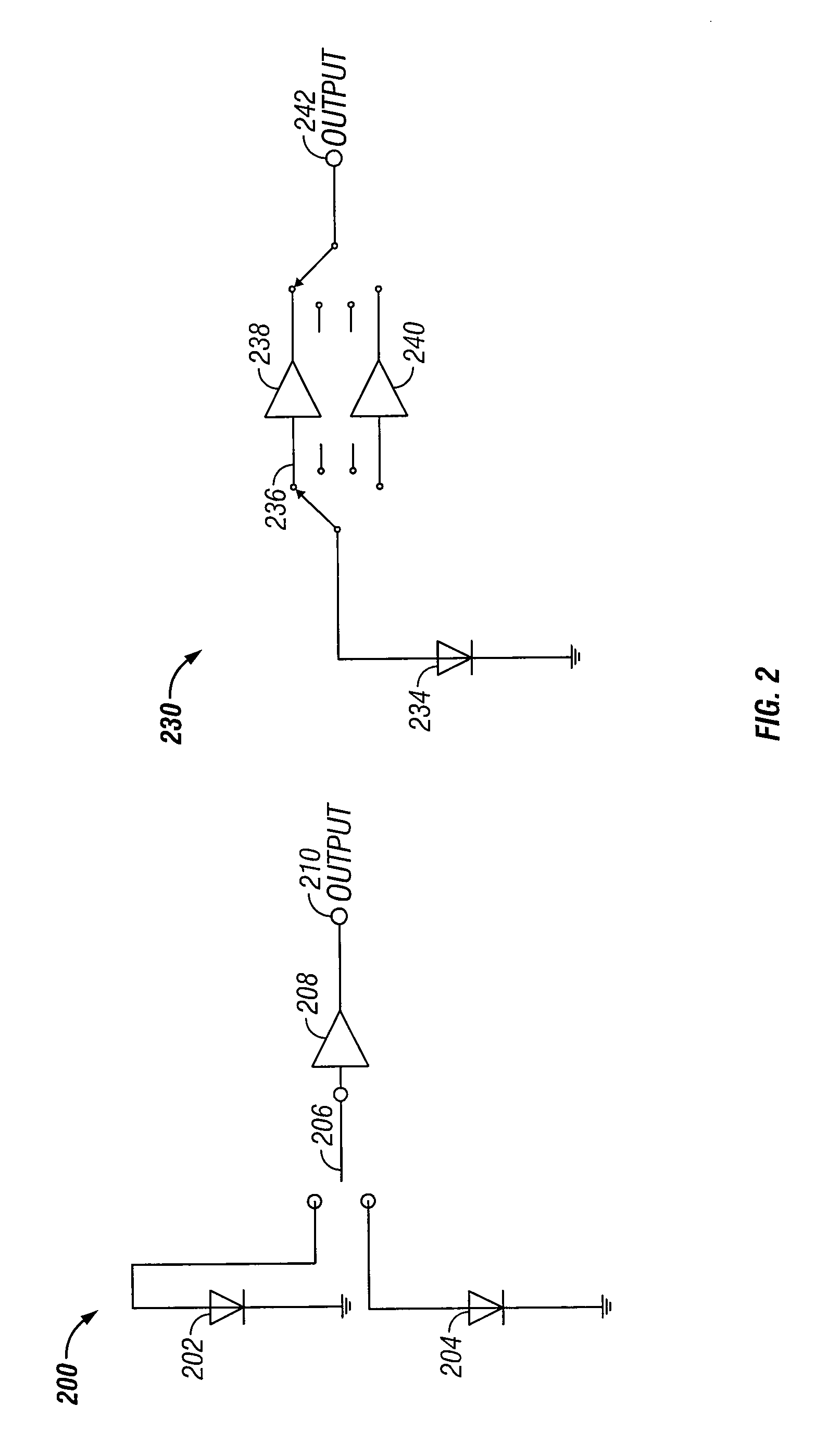
Optical detection apparatus (300) comprising an optical detector (302, 304, 306), a detector amplifier (336, 338, 340), and switching means, e.g., a multiplexer (344, 348), for dynamically selecting at least one of the optical detector or the detector amplifier by switching from among at least two alternative optical detectors and / or at least two detector amplifiers such as to minimize noise equivalent power (NEP) of a selected detector or combination of detector and amplifier under given operating conditions.

Description

BACKGROUND[0001]Downhole fluid samples are often captured during wireline and logging while drilling / measurement while drilling formation exploration. These samples may be used to determine various properties of formation fluid. However, during drilling operations, fluid filtrate invades the formation and tends to contaminate fluids near the well bore. To reduce the level of contamination (e.g., to where the level of fluid contamination remains at or below 5%) during sample acquisition, a considerable length of time may be spent pumping the formation. Thus, field operators are interested to know when the contamination has been reduced to an acceptable level, so that representative samples may be taken.BRIEF DESCRIPTION OF THE DRAWINGS[0002]FIG. 1 is a graph illustrating the noise equivalent power characteristics of selected detector / amplifier combinations according to various embodiments of the invention.[0003]FIG. 2 illustrates schematic diagrams of optical detection apparatus, acc...

Claims


Application Information

Patent Timeline
IPC IPC(8): G01V8/10
CPCE21B47/065G01V8/10G01N21/27E21B47/123E21B47/07E21B47/135E21B49/08G01J2001/4406G01V8/00G01J5/22
Inventor PAI, RAJMORYS, MARIANCOOPER, HOMI PHIROZETHOMAS, JOHN
Owner HALLIBURTON ENERGY SERVICES INC
Learn More