Wind turbine with additional rotor moment of inertia and a method for controlling a wind turbine with additional rotor moment of inertia

a technology of rotor moment and wind turbine, which is applied in the direction of wind turbines, wind energy generation, electrical apparatus, etc., can solve the problems of increasing complexity, requiring extra resources, and changing voltage on the grid, so as to eliminate the need for a brake chopper

Inactive Publication Date: 2013-05-16
ENVISION ENERGY DENMARK
View PDF18 Cites 10 Cited by
  • Summary
  • Abstract
  • Description
  • Claims
  • Application Information

AI Technical Summary

Benefits of technology

[0044]An object of this invention is to disclose a wind turbine and co...

Problems solved by technology

However, at times there is change of voltage on the grid.
The electrical brake system disclosed adds complexity and thereby requires extra resources during production and operation of the wind turbine.
Fu...

Method used


Image

  • Wind turbine with additional rotor moment of inertia and a method for controlling a wind turbine with additional rotor moment of inertia
  • Wind turbine with additional rotor moment of inertia and a method for controlling a wind turbine with additional rotor moment of inertia
  • Wind turbine with additional rotor moment of inertia and a method for controlling a wind turbine with additional rotor moment of inertia

Examples


example

[0176]To illustrate the effect of the invention as disclosed, three wind turbines in the 3.6 MW class are compared. All three wind turbines have a rotor diameter of 128 m (approximately a blade length of 64 m).

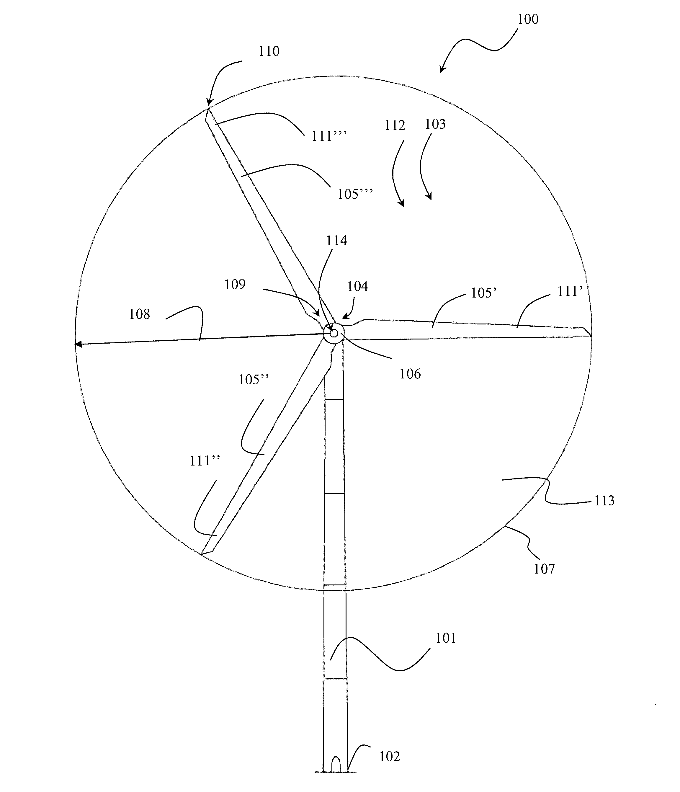
[0177]The first wind turbine is a three bladed active pitch turbine as illustrated in FIG. 1. A blade for this type of wind turbine will have a weight of about 11,000 kg.

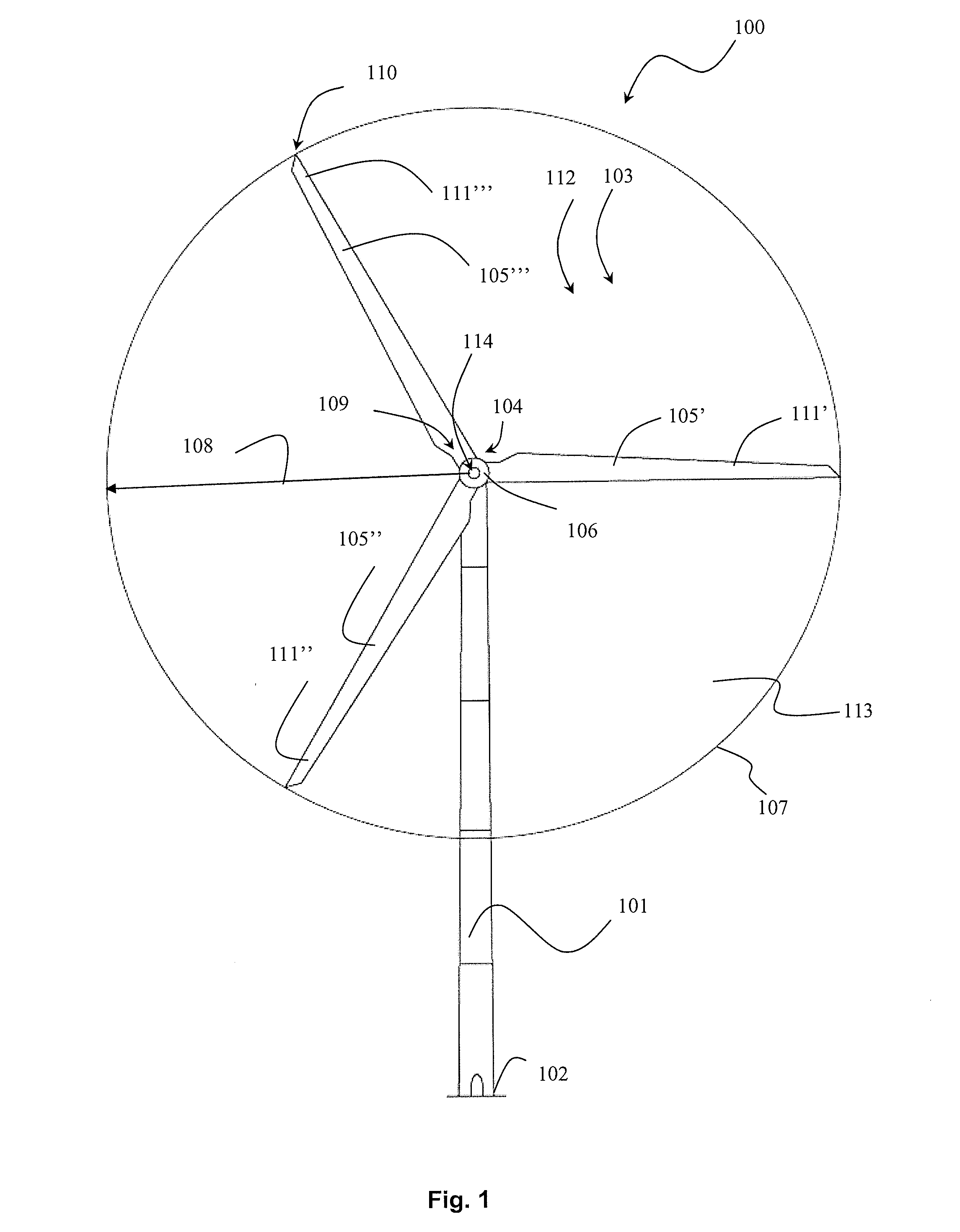
[0178]The second wind turbine is a two bladed active pitch turbine as illustrated in FIG. 2. A blade for this type of wind turbine will have a weight of about 23,000 kg.

[0179]The third wind turbine is a two bladed partial pitch turbine as illustrated in FIG. 5. This is a special embodiment of the disclosure illustrated in FIG. 4. A blade for this third type of wind turbine will have a weight of about 23,000 kg and a pitching system, or pitch bearing, of about 5,000 kg placed at a radius of about 20 m from the axis.

Moment of InertiaTypeBladeWeight[kgm2]1Three blade, active pitch11,000 kg21 × 1062Two blade, acti...


PUM


Abstract

This invention relates to a wind turbine having an additional mass each placed between a mounting end and a free end of at least two rotor blades. This invention further relates to a method for controlling a wind turbine with a pitch system for pitching a blade in a pitch angle and with blades with a mass for increased inertia, which wind turbine is operated in a normal operation mode in which a generator has a generator speed at a generator torque, and which wind turbine is to remain electrically coupled to a grid during a low voltage condition and with supplied current specifications, torque reference, power references, or according to a grid code.

Description

BACKGROUND OF THE INVENTION[0001]1. Field of the Invention[0002]This invention relates to a wind turbine comprising:[0003]a wind turbine tower with an upper end and a lower end, which lower end is provided on a wind turbine foundation;[0004]a wind turbine nacelle provided at an upper end of said tower;[0005]a hub provided at said nacelle;[0006]at least two wind turbine rotor blades each with a mounting end and a free end, which mounting end is mounted on the hub for rotation in a rotational plane around an axis that is extended by shaft coupled to a generator or a gearbox;[0007]grid connection for feeding produced electricity from the generator to a grid, which grid connection has voltage detection means for detecting changes in the voltage on the grid;[0008]at least two masses each placed between the mounting end and the free end of at least two rotor blades.[0009]2. Description of Related Art[0010]This invention further relates to a method for controlling a wind turbine with a pit...

Claims


Application Information

Patent Timeline
IPC IPC(8): F03D7/02
CPCF03D7/02F03D7/0284Y02E10/725Y02E10/723Y02E10/721Y02E10/72
Inventor BIRK, JENS
Owner ENVISION ENERGY DENMARK
Why Eureka
Try Eureka