

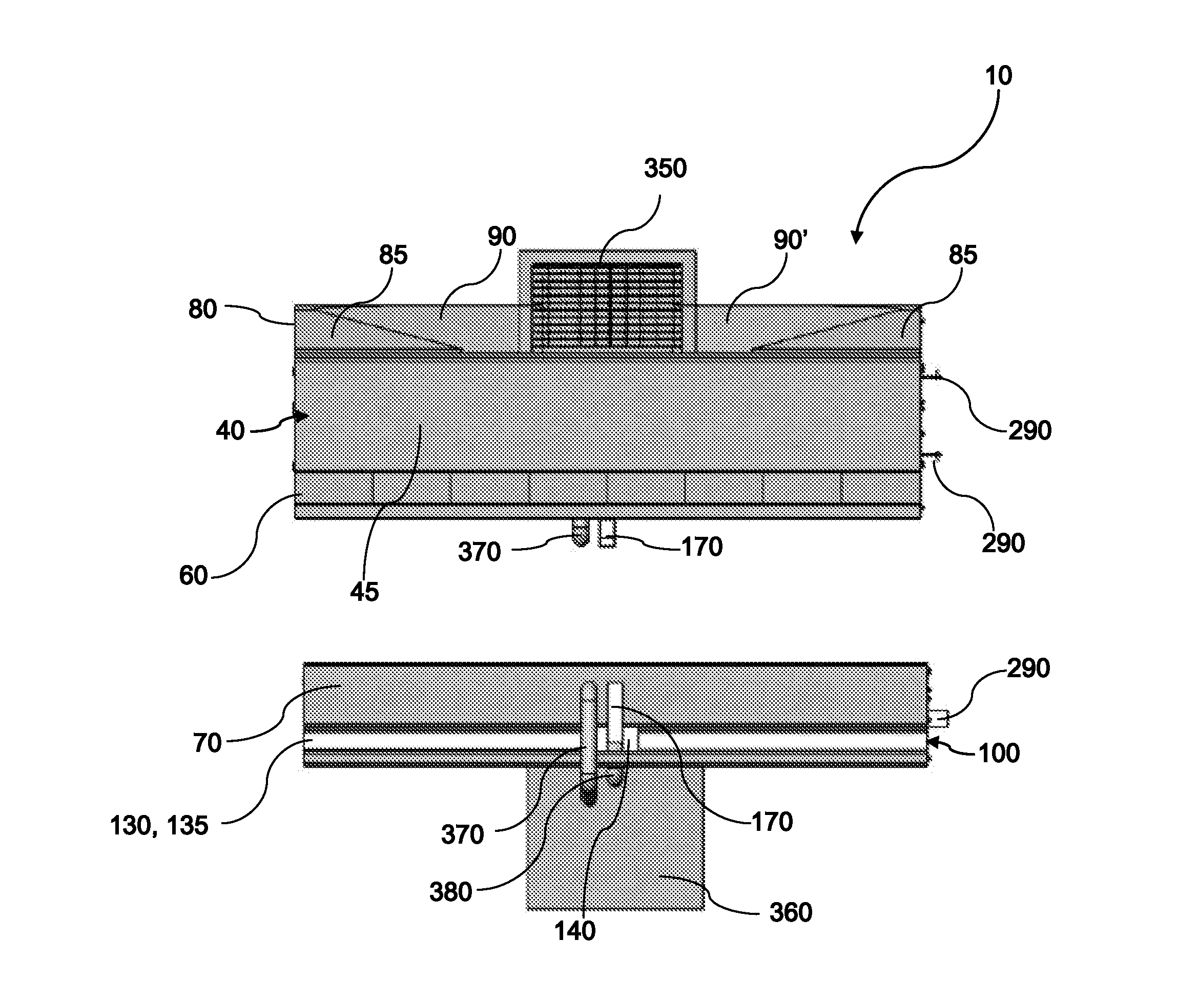
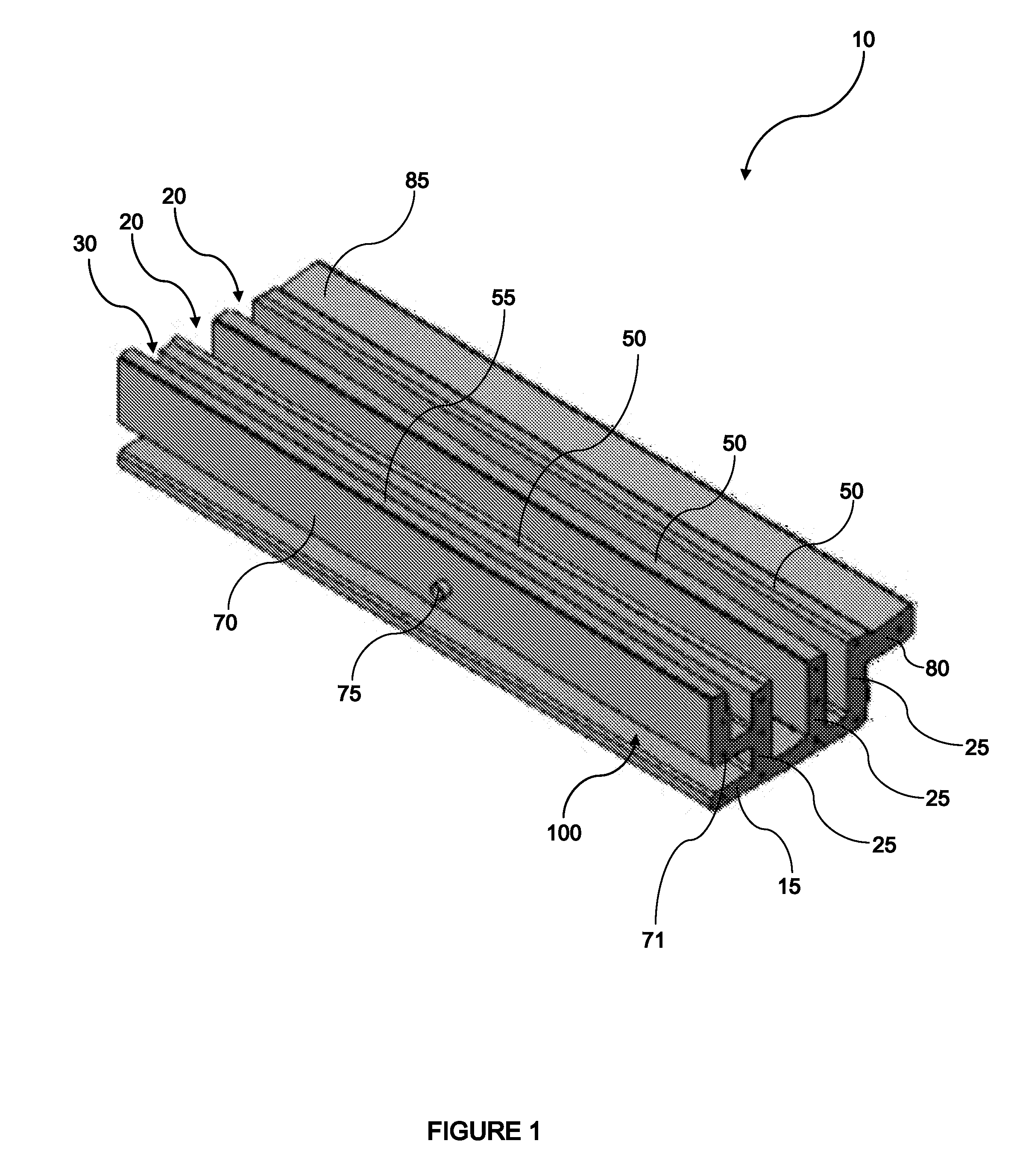
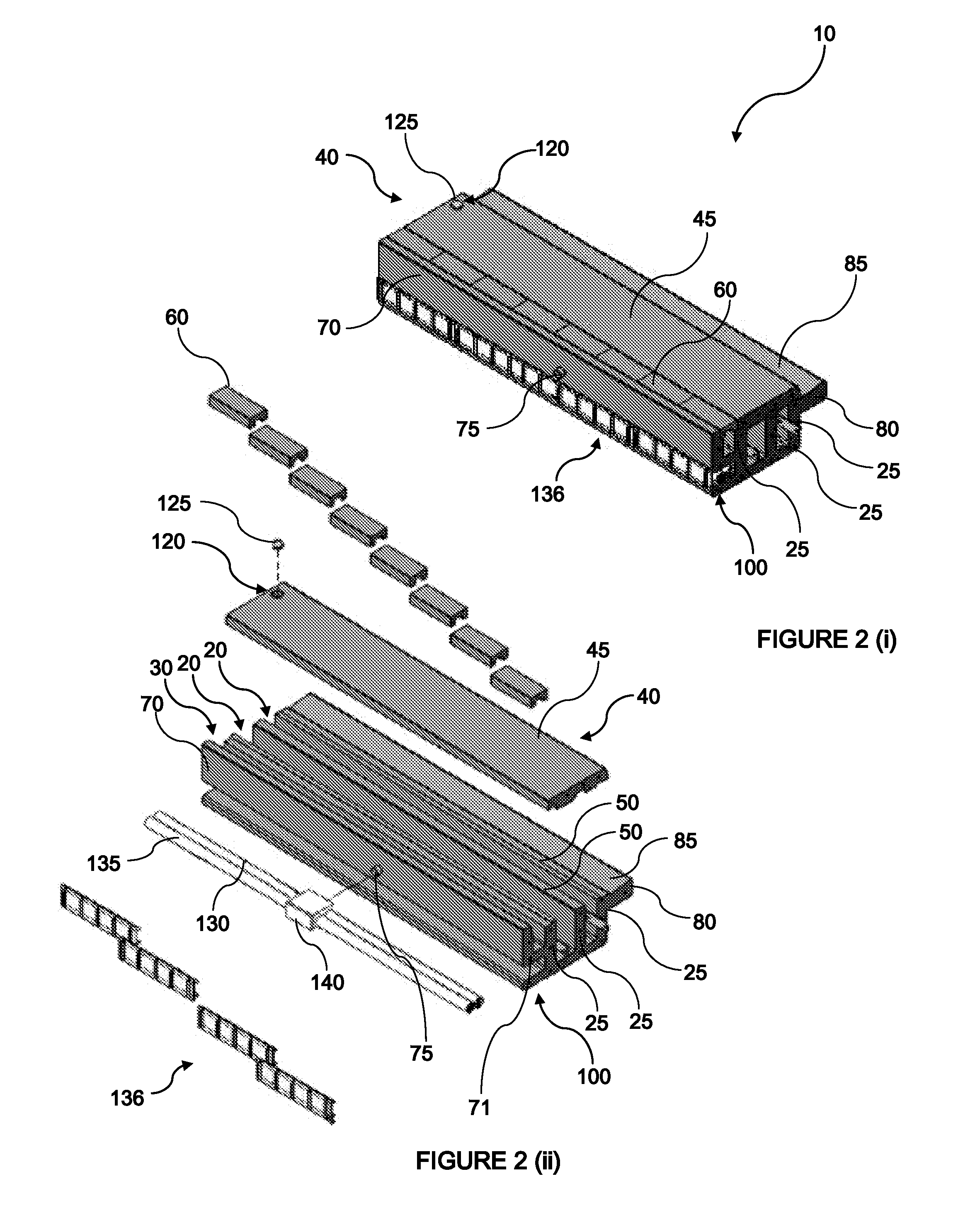
Modular Ducting Section Adapted for Laing End-To-End and Side by Side Forming a Networked Utilities Ducting System and Rain and Run-Off Water Management System
a technology of ducting section and networked utilities, applied in the field of modular ducting section, can solve the problems of reducing the aesthetics of the streetscape and the value of the surrounding property, preventing high-sided vehicles such as lorries from being able to safely pass under the cables, and achieving low-cost installation and cost advantages. , the effect of cost saving
- Summary
- Abstract
- Description
- Claims
- Application Information
AI Technical Summary
Benefits of technology
Problems solved by technology
Method used
Image

Examples
embodiments
[0453]Reference throughout this specification to “one embodiment” or “an embodiment” means that a particular feature, structure or characteristic described in connection with the embodiment is included in at least one embodiment of the present invention. Thus, appearances of the phrases “in one embodiment” or “in an embodiment” in various places throughout this specification are not necessarily all referring to the same embodiment, but may. Furthermore, the particular features, structures or characteristics may be combined in any suitable manner, as would be apparent to one of ordinary skill in the art from this disclosure, in one or more embodiments.
[0454]Similarly it should be appreciated that in the above description of example embodiments of the invention, various features of the invention are sometimes grouped together in a single embodiment, Figure, or description thereof for the purpose of streamlining the disclosure and aiding in the understanding of one or more of the vario...
PUM
 Abstract
Description
Claims
Application Information