Exhaust heating apparatus for internal combustion engine and control method for the same

Inactive Publication Date: 2013-05-23
TOYOTA JIDOSHA KK
View PDF0 Cites 13 Cited by
  • Summary
  • Abstract
  • Description
  • Claims
  • Application Information

AI Technical Summary

Benefits of technology

[0018]With the present invention, even in an internal combustion engine in which 2-stage exhaust turbochargers are incorporated, it is possible to stably actuate the exhaust heating apparatus not only at the time of decelerating but even at the time of accelerating or traveling at constant speed when the internal combustion engine is in the low rotational speed range. This is the same even when in the operating state where the first exhaust passage can be closed. The heated gas can be efficiently mixed with the exhaust gas flowing in the second exhaust passage at the confluent portion with the second exhaust passage.
[0019]When an oxidation catalyst is arranged in the exhaust passage between ignition means and the exhaust emission purifier, it is possible to further efficiently increase the temperature of the heated gas.
[0020]When a valve that is capable of adjusting a flow of exhaust that flows in the first exhaust passage is arranged in the first exhaust passage further on the upstream side than an exhaust turbine of a first exhaust turbine type

Problems solved by technology

A turbocharger that comparatively easily achieves an improvement in output from an internal co

Method used


Image

  • Exhaust heating apparatus for internal combustion engine and control method for the same
  • Exhaust heating apparatus for internal combustion engine and control method for the same
  • Exhaust heating apparatus for internal combustion engine and control method for the same

Examples


Embodiment Construction

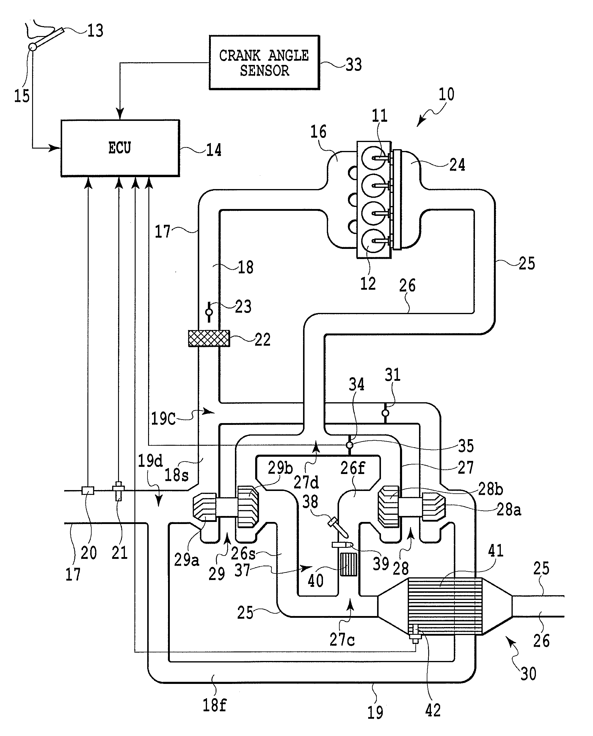
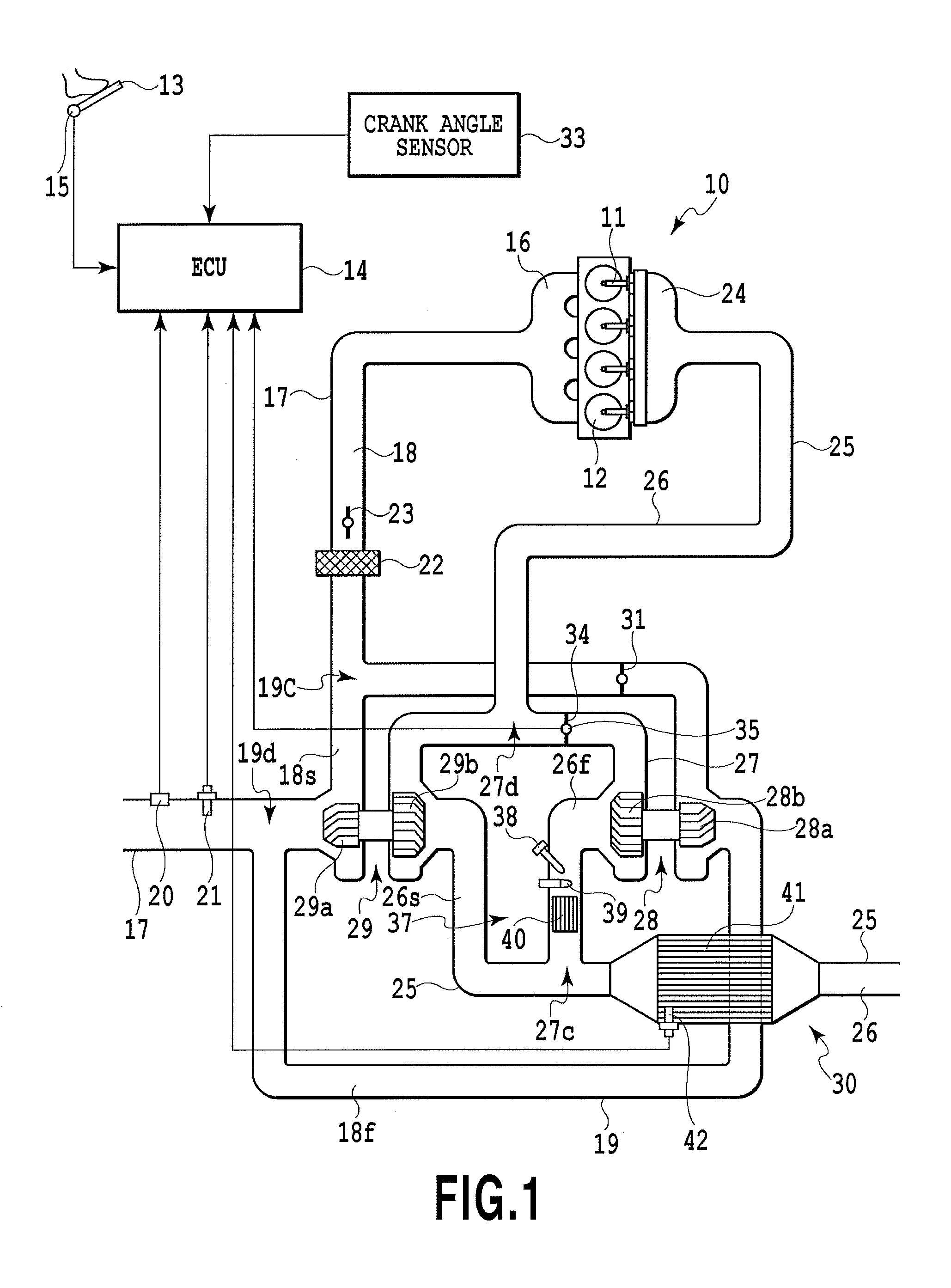
[0028]An embodiment in which the present invention is applied to a compression ignition type internal combustion engine in which parallel-type 2-stage exhaust turbochargers are incorporated will be explained in detail with reference to FIGS. 1 to 4. The present invention is not, however, limited to the embodiment, and the construction thereof may be freely modified corresponding to required characteristics. The present invention is effectively applied to a spark ignition type internal combustion engine in which gasoline, alcohol, LNG (Liquefied Natural Gas) or the like is used as fuel to be ignited by a spark plug, for example.

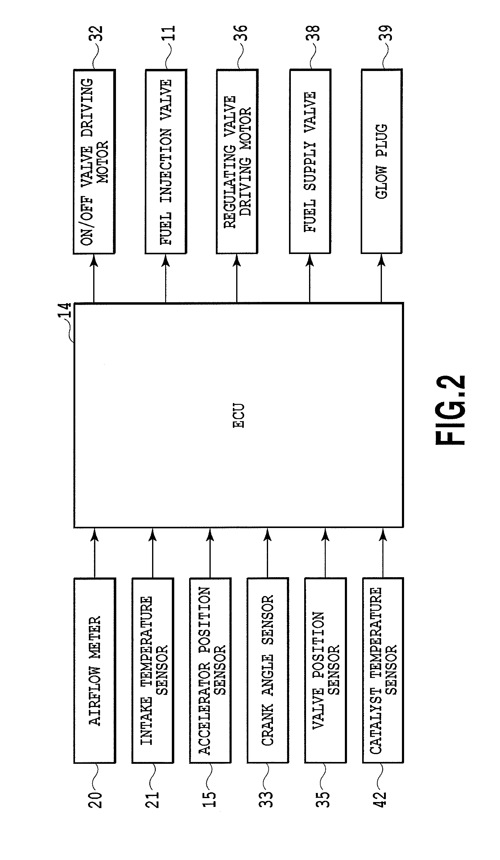
[0029]Main components of an engine system of the embodiment are illustrated schematically in FIG. 1, and a control block thereof is illustrated in FIG. 2, however, a valve mechanism for intake and exhaust, an EGR system, and the like are omitted for convenience. The engine 10 according to the present embodiment is a compression-ignition multicylinder (four cyl...


PUM


Abstract

An exhaust heating apparatus (37) according to the present invention, for heating exhaust being led to an exhaust emission purifier (30) from an internal combustion engine (10) in which a first exhaust turbocharger (28) and a second exhaust turbocharger (29) that is mainly used in a lower rotational speed range of the engine than the first turbocharger are incorporated, is arranged in a first exhaust passage (26f) that is located further upstream than a confluent portion (27c) of the first exhaust passage, which passes through an exhaust turbine (28b) of the first turbocharger and continues to the exhaust emission purifier, and a second exhaust passage (26s), which goes around the exhaust turbine of the first turbocharger and passes through an exhaust turbine (29b) of the second turbocharger and continues to the exhaust emission purifier, and further downstream than the exhaust turbine of the first turbocharger.

Description

TECHNICAL FIELD[0001]The present invention relates to an exhaust heating apparatus that increases a temperature of exhaust in order to activate an exhaust emission purifier and keep the exhaust emission purifier in an activated state in an internal combustion engine that is provided with the exhaust emission purifier.BACKGROUND ART[0002]A turbocharger that comparatively easily achieves an improvement in output from an internal combustion engine also has a tendency at the same time to bring about a drop in fuel efficiency. In recent years, in order to meet the strong demand for an improvement in the fuel efficiency of internal combustion engines in which this kind of turbocharger is incorporated, internal combustion engines in which two turbochargers having different characteristics are incorporated are proposed in Patent Literature 1 and Patent Literature 2. In either case, there are provided a first turbocharger that mainly functions in a low rotational speed range of the internal ...

Claims


Application Information

Patent Timeline
IPC IPC(8): F01N5/00F01N3/08
CPCF01N3/103F01N3/2033F01N13/02F01N2610/03F02B37/007F01N13/0093Y02T10/26F02B37/002F02B37/004F02B37/013F01N5/00Y02T10/144Y02T10/12
Inventor HAYAKAWA, TAKESHI
Owner TOYOTA JIDOSHA KK
Why Eureka
Try Eureka