Method and apparatus for optimizing the operation of a turbine system under flexible loads

a technology of flexible load and turbine system, which is applied in the direction of mechanical equipment, machines/engines, light and heating equipment, etc., can solve the problems of chaotic electricity demand, inability to efficiently store electricity generated by power companies, and impact demand, so as to improve the efficiency of the combined cycle gas turbine and extend the turndown range of the gas turbine system

Active Publication Date: 2013-05-23
GENERAL ELECTRIC CO
View PDF9 Cites 91 Cited by
  • Summary
  • Abstract
  • Description
  • Claims
  • Application Information

AI Technical Summary

Benefits of technology

[0017]According to another aspect of the present invention a method of extending the turndown range of the gas turbine system is provided. The method includes establishing minimum air flow parameters for air flowing through the compressor; conveying turbine exhaust from the turbine to a mixing assembly at a first flow rate; conveying compressed air from the compressor to the mixing assembly at a second flow rate; and controlling the first flow rate and the second flow rate to maintain the compressor airflow above the minimum air flow parameters.
[0018]According to another aspect of the present invention a method of improving the efficiency of the combined cycle gas turbine at partial load is provided. The method includes maintaining an air flow through a compressor at an airflow coefficient for the partial load above a minimum flow rate coefficient where aeromechanical stresses occur in the compressor; maintaining an air fuel ratio in a combustor where exhaust gas emission components from the turbine are maintained below a predetermined component emission level; and maintaining an exhaust gas temperature at an inlet of a heat recirculation steam generator below a predetermined maximum inlet temperature.

Problems solved by technology

Electricity demand is chaotic.
Weather and season of the year also impact demand.
Because electricity generated by power companies cannot be efficiently stored, electric utilities have traditionally generated power with a combination of different approaches to production.
The peak load of a gas turbine is a load that maximizes power output, frequently at the expense of efficiency, parts life and inspection intervals.
However, operation at low loads results in lower operating efficiencies and higher operating costs.
Compliance with emission standards is also a major constraint in the operation of gas turbines.
Consequently, there is a limit to the load level at which conventional gas turbine systems may be operated while still complying with emission standards.
Some plants may be limited on the basis of the number of tons of NOx emitted per year or other time period (periodic limit).
One of the problems with the operation of gas turbines over wide power ranges is that efficiency, fuel consumption and emissions, specifically, NOx and CO emissions, may be negatively affected.
For example, when a plant operator operates a conventional gas turbine at low loads there is a significant decrease in efficiency.
Another problem is that the compressor may be subjected to aeromechanical stresses in the aft stages when the gas-fired turbine is operated at lower loads in low ambient temperature conditions.
Yet another problem with gas turbines operating at lower ambient temperatures is that the minimum load required for CO compliance is a function of, among other things, the ambient temperature.
Yet another problem is that the use of a heat recovery steam generator in a combined cycle gas turbine systems may impose additional constraints on the optimal gas turbine operation at base-load, part-load and load-ramp operating modes.
Yet another problem is that when the gas turbine is operated at extreme low hibernation modes of approximately 10% load there is the potential of combustor lean blowout (i.e. loss of flame).

Method used


Image

  • Method and apparatus for optimizing the operation of a turbine system under flexible loads
  • Method and apparatus for optimizing the operation of a turbine system under flexible loads
  • Method and apparatus for optimizing the operation of a turbine system under flexible loads

Examples


Embodiment Construction

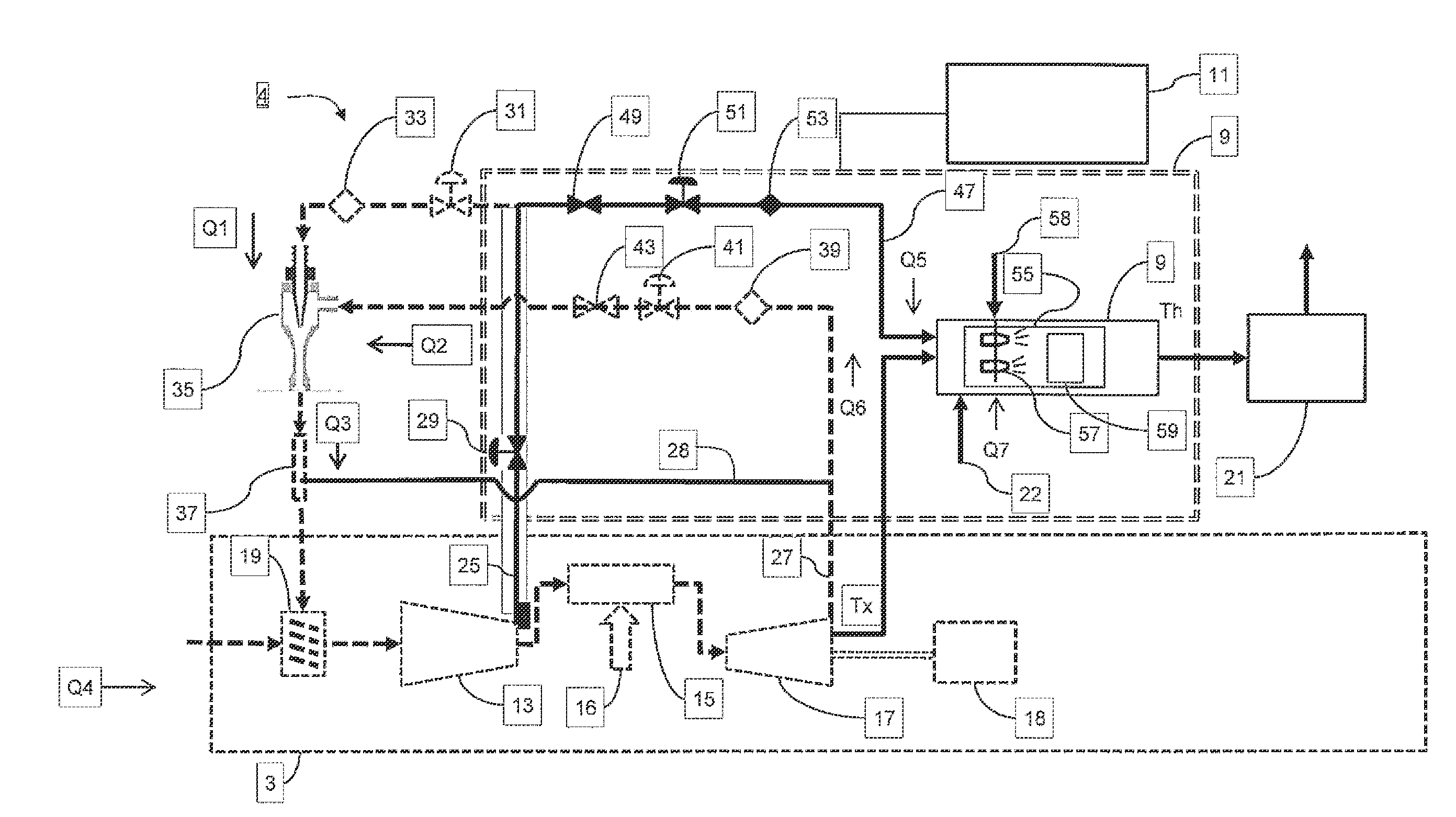
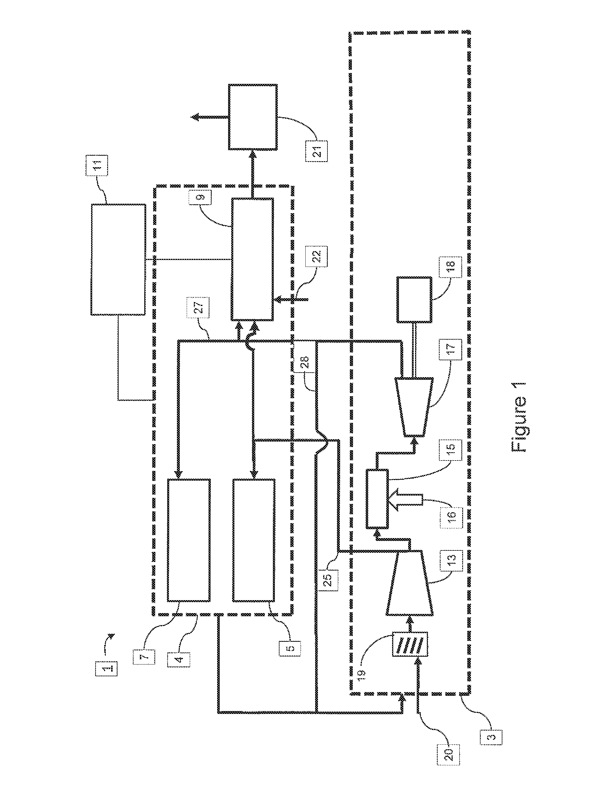
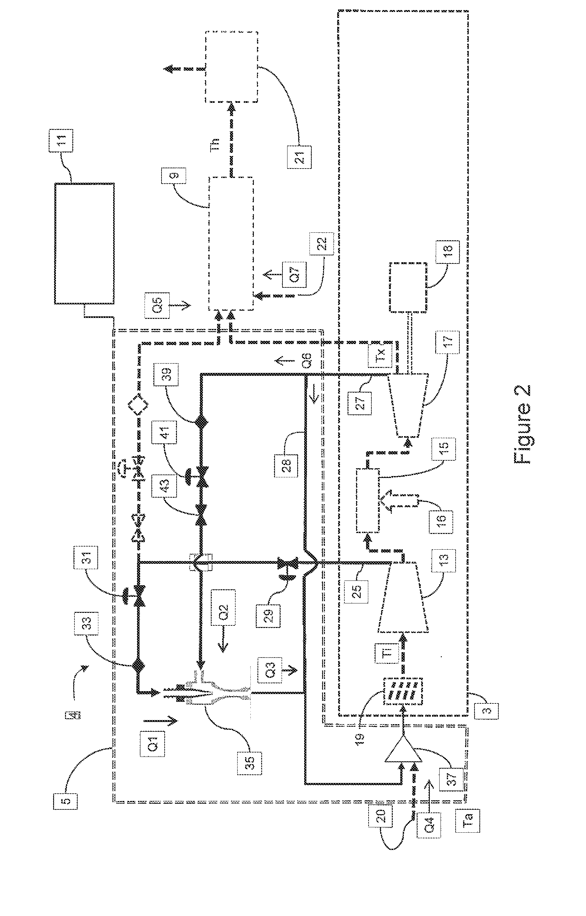
[0033]FIG. 1 illustrates a high-level schematic of an embodiment of a gas turbine system 1. The gas turbine system 1 includes a conventional gas turbine 3, turndown subsystem 4, and a control subsystem 11. The turndown subsystem 4 may include a compressor protection subsystem 5, a hibernation mode subsystem 7 and a combined cycle isotherm subsystem 9.

[0034]The gas turbine 3 may include a compressor 13, a combustor 15, a turbine 17, a generator 18, an inlet guide vane (IGV) subsystem 19 and a heat recovery steam generator (heat recovery steam generator subsystem 21) subsystem 21. In operation, ambient air 20 is drawn through the IGV subsystem 19 and enters the compressor 13. The temperature, pressure and relative humidity of ambient air 20 will obviously vary. For comparative purposes, the turbine industry has established standard conditions for ambient air. The standard conditions are 59° F. / 15° C., 14.696 psia / 1.013 bar and 60% relative humidity. The IGV subsystem 19 serves to vary...


PUM


Abstract

A gas turbine system includes a compressor protection subsystem; a hibernation mode subsystem; and a control subsystem that controls the compressor subsystem and the hibernation subsystem. At partial loads on the turbine system, the compressor protection subsystem maintains an air flow through a compressor at an airflow coefficient for the partial load above a minimum flow rate coefficient where aeromechanical stresses occur in the compressor. The air fuel ratio in a combustor is maintained where exhaust gas emission components from the turbine are maintained below a predetermined component emission level while operating at partial loads.

Description

TECHNICAL FIELD[0001]The present invention relates to gas turbine systems, and more particularly to apparatus and methods for optimizing the operation of a turbine system under flexible loads.BACKGROUND[0002]As a result of continuing global population and income growth, electricity demand continues to increase worldwide. Electricity grids are required to adjust to large somewhat unpredictable swings in demand as well as the planned and unplanned changes in production capacity. Additionally, alternative sources such as wind and solar generated power are growing in importance and these sources have an impact in the way that power is generated to meet the demand.[0003]Electricity demand is chaotic. Demand may vary on a daily, monthly, seasonal and yearly cycles. For example, a typical residential daily demand profile on a hot day may show a minimum in the early morning hours, and a maximum in the early evening hours. Commercial demand on the same day may show a minimum in the early eve...

Claims


Application Information

Patent Timeline
Patent Type & Authority Applications(United States)
IPC IPC(8): F02C9/00
CPCF02C9/22F02C9/26Y02E20/16Y02E20/18Y02E20/14F05D2270/08F05D2270/3061F05D2270/313F02C3/34F02C7/057F05D2220/722F05D2260/601F02C9/48F02C9/28F23R3/26F01K23/10F02C3/13F02C9/18
Inventor SCIPIO, ALSTON I.FREEMAN, THOMAS JOHNOBENHOFF, RYAN ERICEKANAYAKE, SANJICOCCA, MICHAEL ANTHONYYARNOLD, MIKEWARWICK, DOUGLAS CORBINKLOSINSKI, JOSEPH
Owner GENERAL ELECTRIC CO
Why Eureka
Try Eureka