


Quick Research
Generate reliable direction feasibility study reports for your R&D in just a few steps.

Technical Q&A
Discover and master advanced knowledge NOW. Basics, ideas, possibilities, all at once.

Find Solutions
As an expert in R&D theories, this can generate solutions to your technical problems instantly.

Evaluate Feasibility
Analyze your overall solution with one click, know your potential R&D risks in advance.

Monitor Landscape
Get weekly tech updates, stay abreast of the latest tech innovations and key insights.
Carbon dioxide immobilization unit
- Summary
- Abstract
- Description
- Claims
- Application Information
AI Technical Summary
Benefits of technology
Problems solved by technology
Method used
Image

Examples
first embodiment
1. First Embodiment
Entire Configuration of Cell
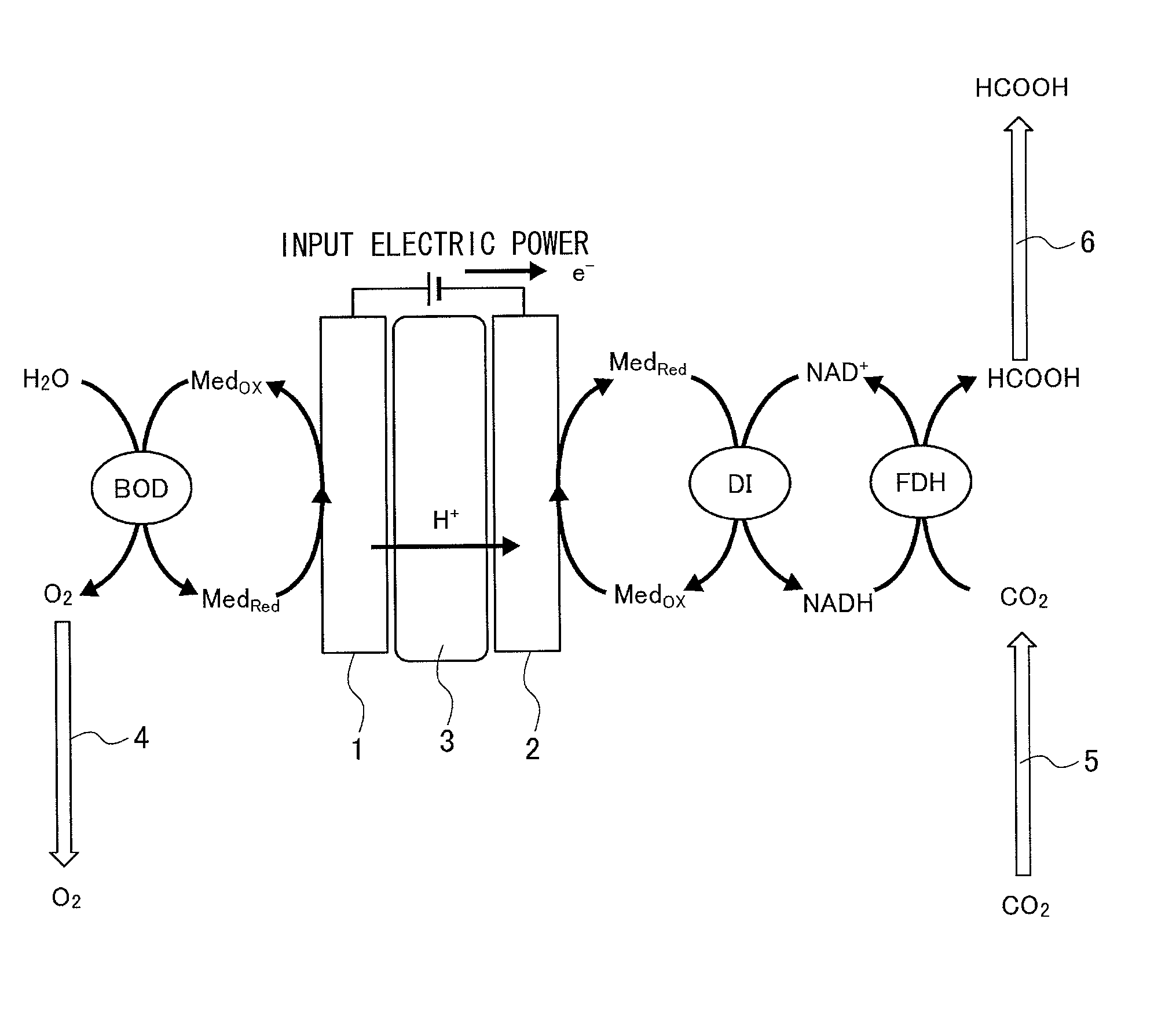
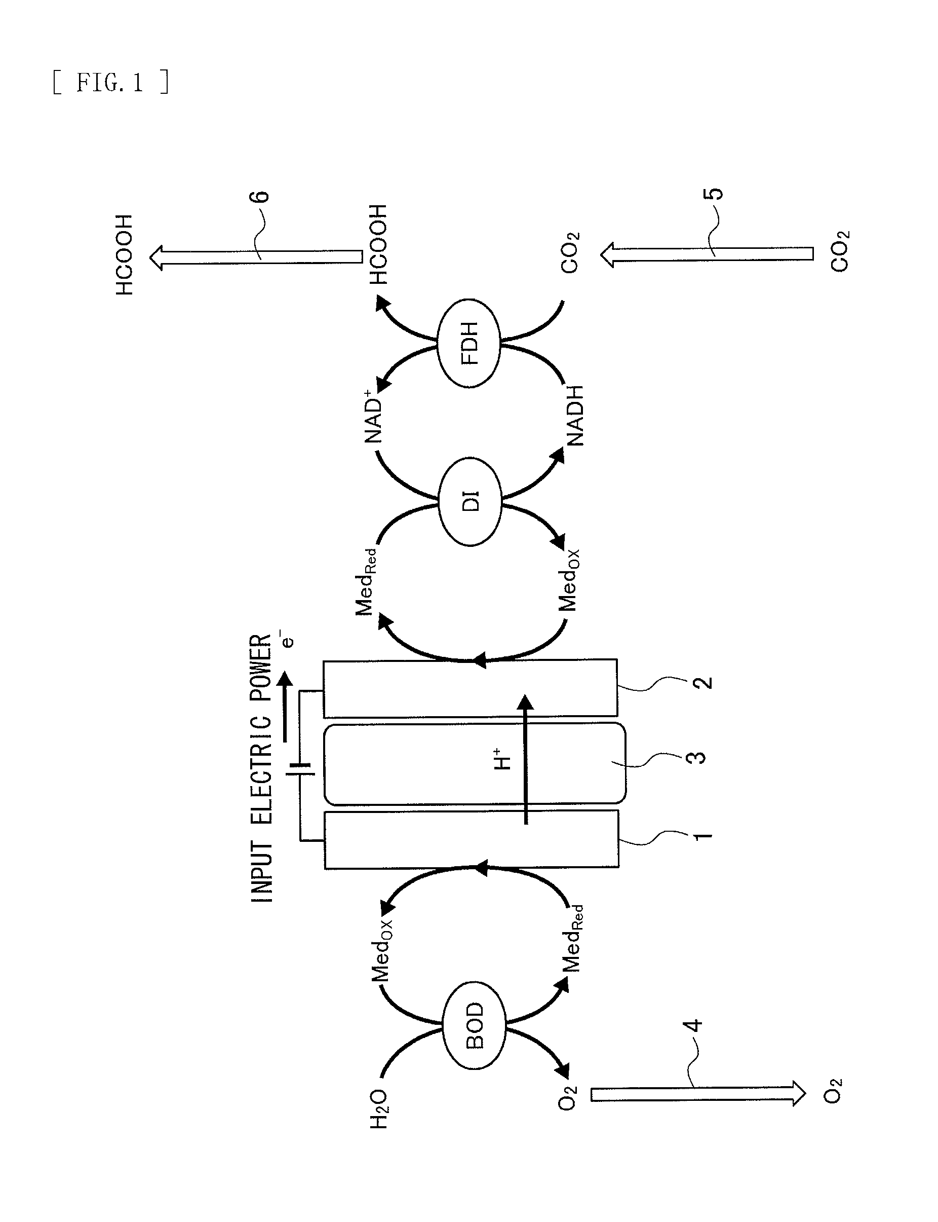
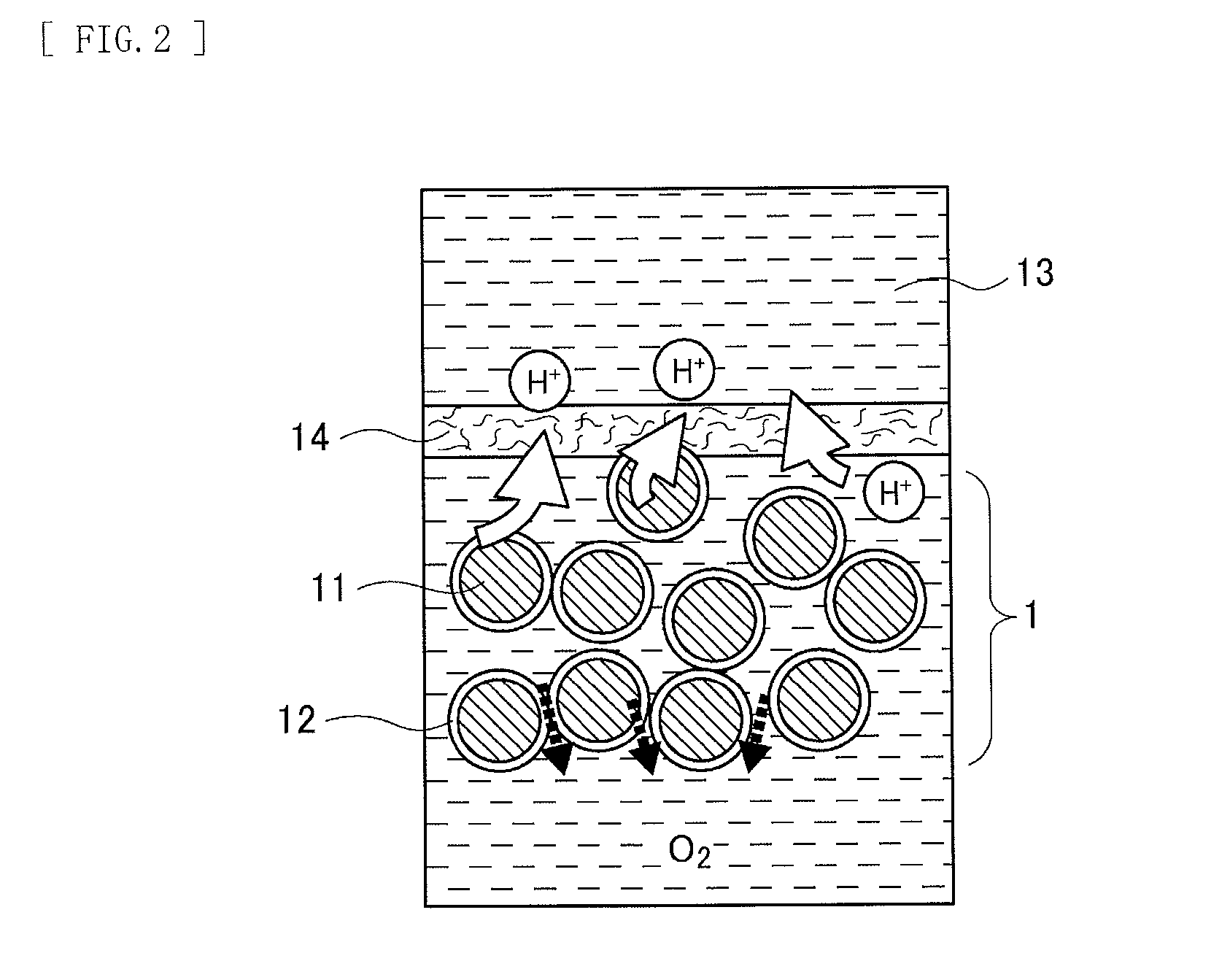
[0032]FIG. 1 is a diagram schematically illustrating a carbon dioxide immobilization unit according to an embodiment of the invention. Moreover, FIG. 2 is a diagram schematically illustrating an electrode configuration of an anode 1 (a first electrode) which is of a dipping type, and FIG. 3 is a diagram schematically illustrating an electrode configuration of a cathode 2 (a second electrode) which is of a semi-dipping type. As illustrated in FIG. 1, the carbon dioxide immobilization unit according to the embodiment includes the anode 1 and the cathode 2 which are disposed to face each other with a proton conductor 3 in between.
[0033]In the carbon dioxide immobilization unit, an oxidoreductase is present on a surface of the anode 1 or a surface of the cathode 2, or both, and an organic acid such as formic acid or a carbohydrate such as glucose is produced from carbon dioxide (CO2) by reaction opposite to reaction in a biofuel cell in rel...
modification example
2. Modification Example of First Embodiment
Entire Configuration of Cell
[0063]In the above-described embodiment, the carbon dioxide immobilization unit producing formic acid from carbon dioxide is described; however, the present invention is not limited thereto, and the carbon dioxide immobilization unit is allowed to produce a carbohydrate such as methanol or glucose in addition to the organic acid such as formic acid.
[0064]FIG. 4 is a diagram schematically illustrating a principle of a carbon dioxide immobilization unit according to a modification example of the above-described embodiment. It is to be noted that, in FIG. 4, like components are denoted by like numerals as of the carbon dioxide immobilization unit according to the first embodiment illustrated in FIG. 1 and will not be further described. As illustrated in FIG. 4, the carbon dioxide immobilization unit according to the modification example also includes an anode 31 and a cathode 32 which are disposed to face each other...
PUM
| Property | Measurement | Unit |
|---|---|---|
| Concentration | aaaaa | aaaaa |
| Electrical conductor | aaaaa | aaaaa |
Abstract
Description
Claims
Application Information
 - R&D Engineer
- R&D Manager
- IP Professional
- Industry Leading Data Capabilities
- Powerful AI technology
- Patent DNA Extraction
Browse by: Latest US Patents, China's latest patents, Technical Efficacy Thesaurus, Application Domain, Technology Topic, Popular Technical Reports.
© 2024 PatSnap. All rights reserved.Legal|Privacy policy|Modern Slavery Act Transparency Statement|Sitemap|About US| Contact US: help@patsnap.com