Analyte sensors having a signal-to-noise ratio substantially unaffected by non-constant noise

a technology of analyte sensor and non-constant noise, applied in the field of analyte sensor, can solve the problems of likely diabetic behavior, inhibiting the ability of diabetics to make educated insulin therapy decisions

Active Publication Date: 2013-05-23
DEXCOM
View PDF5 Cites 128 Cited by
  • Summary
  • Abstract
  • Description
  • Claims
  • Application Information

AI Technical Summary

Benefits of technology

[0023]In an embodiment of the first aspect, the signal contribution due to the non-constant non-analyte-related component is less than about 10% of the signal over a time period of at least about one day.
[0024]In an embodiment of the first aspect, the signal contribution due to the non-constant non-analy

Problems solved by technology

In the diabetic state, the victim suffers from high blood sugar, which may cause an array of physiological derangements (for example, kidney failure, skin ulcers, or bleeding into the vitreous of the eye) associated with the deterioration of small blood vessels.
Conventionally, a diabetic person carries a self-monitoring blood glucose (SMBG) monitor, which typically comprises uncomfortable finger pricking methods.
Unfortunately, these time int

Method used


Image

  • Analyte sensors having a signal-to-noise ratio substantially unaffected by non-constant noise
  • Analyte sensors having a signal-to-noise ratio substantially unaffected by non-constant noise
  • Analyte sensors having a signal-to-noise ratio substantially unaffected by non-constant noise

Examples


example 1

Resistance Domain Configurations to Increased the Analyte Signal Reduce Non-Constant Noise

[0412]Transcutaneous sensors, with electrode, interference, enzyme and resistance (polyurethane blend) domains, were built and tested in non-diabetic hosts. The control and test sensors were built as described in U.S. Publication No. 2006-0020187, which is incorporated herein by reference in its entirety, with the following exception: the resistance domain of the test sensors was formed of 3 layers of a 60% ChronoThane® H (CardioTech International, Wilmington, Mass., USA; the PEO concentration of ChronoThane® H is about 25%) polyurethane blend solution, as compared to a single layer of a 45% ChronoThane® H polyurethane blend solution in the control sensors. Test and control sensors were implanted bilaterally in the abdomens of non-diabetic host volunteers, for a period of about 7 days.

[0413]FIG. 8 illustrates exemplary test results from one test sensor, over a period of about 7 days, after sens...

example 2

A Lubricious Coating Configured to Reduce Non-Constant Noise

[0416]Control and test sensors, with electrode, enzyme and resistance domains, were built as described in U.S. Patent Publication No. US-2006-0020187-A1, including a resistance domain formed using a polyurethane polymer blend having about 8 wt. % PEO, as described in the section entitled “Polyurethane Polymer Material” above. A lubricious coating was applied to the test sensors by dipping them one time into a solution of HydroMed™ (CardioTech International, Inc., Wilmington, Mass., USA) and drying. The control and test sensors were tested in vitro (see Table 1, below). The test sensors (with the lubricious coating) had a substantially increased sensitivity (m) but with no corresponding increase in constant noise (b), when compared to control sensors (no lubricious coating). Accordingly, it was shown that application of a lubricious coating over a polyurethane blend resistance domain of a glucose sensor can (in vitro) substa...

example 3

Discontinuous Hydrophilic Overcoat on Resistance Domain Configured to Reduce Non-Constant Noise

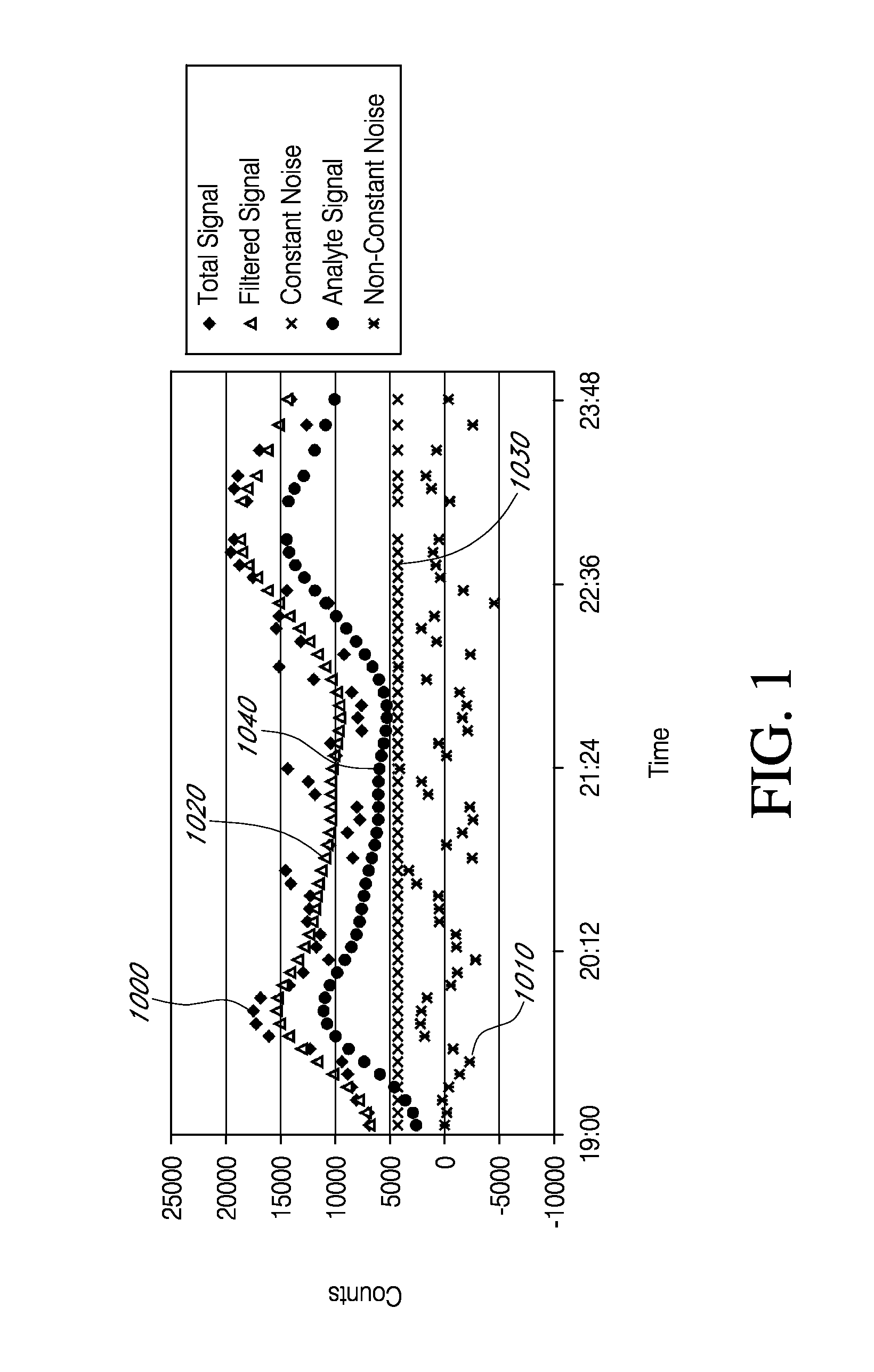
[0418]To determine if a hydrophilic overcoat on the resistance layer can increase the analyte signal component and / or reduce the non-constant noise component, test and control sensors were build and tested in volunteer human hosts, over a period of 3 days. Both the test and control sensors included an electrode layer, an enzyme layer and a polyurethane blend resistance domain. The polyurethane blend used to form the resistance domain included 8% hydrophile (i.e., PEO). After fabrication, the test sensors were sprayed (one time) in a solution of 5% ChronoThane® H (about 25% PEO; CardioTech International, Wilmington, Mass., USA) and cured. Test and control sensors were implanted bilaterally in the abdomens of the volunteer human hosts. FIG. 10 is a graph showing test results from one exemplary sensor. Components of the Total Signal 1000 were determined, as described in Example 1. The Y-axis ...


PUM


Abstract

Systems and methods of use involving sensors having a signal-to-noise ratio that is substantially unaffected by non-constant noise are provided for continuous analyte measurement in a host. In some embodiments, a continuous analyte measurement system is configured to be wholly, transcutaneously, intravascularly or extracorporeally implanted.

Description

CROSS-REFERENCE TO RELATED APPLICATIONS[0001]This application is a continuation of U.S. patent application Ser. No. 11 / 750,907, filed May 18, 2007, which is a continuation-in-part of U.S. patent application Ser. No. 11 / 675,063, filed Feb. 14, 2007, which is a continuation-in-part of U.S. patent application Ser. No. 11 / 404,417, filed Apr. 14, 2006. U.S. patent application Ser. No. 11 / 675,063 is also a continuation-in-part of U.S. patent application Ser. No. 10 / 896,639, filed Jul. 21, 2004, which claims the benefit of U.S. Provisional Application No. 60 / 490,009, filed Jul. 25, 2003. U.S. patent application Ser. No. 11 / 750,907 is also a continuation-in-part of U.S. application Ser. No. 11 / 404,417, filed Apr. 14, 2006. Each of the aforementioned applications is incorporated by reference herein in its entirety, and each is hereby expressly made a part of this specification.FIELD OF THE INVENTION[0002]The preferred embodiments relate generally to implantable devices, such as analyte senso...

Claims


Application Information

Patent Timeline
IPC IPC(8): A61B5/1486A61B5/145A61B5/00A61B5/1473
CPCA61B5/1411A61B5/14532A61B5/14546A61B5/14865A61B5/7203A61B5/1473A61B5/14735A61B5/1486A61B5/6848A61B5/00
Inventor SIMPSON, PETER C.BOOCK, ROBERT J.PETISCE, JAMES R.BRISTER, MARK C.RIXMAN, MONICA A.WOO, KUM MINGNGUYEN, LISABRUNNER, SETH R.CHEE, ARTHURNICHOLAS, MELISSA A.WIGHTLIN, MATTHEW D.PRYOR, JACKMARKOVIC, DUBRAVKA
Owner DEXCOM
Why Eureka
Try Eureka