Bone screw introducing sleeve

a bone screw and sleeve technology, applied in the field of medical devices, can solve the problems of reducing the blood supply of the fractured bone, affecting the healing process, so as to reduce the trauma of the patient, reduce the risk of fracture, and improve the healing process.

Inactive Publication Date: 2013-05-23
FARRELL ERIC D
View PDF8 Cites 14 Cited by
  • Summary
  • Abstract
  • Description
  • Claims
  • Application Information

AI Technical Summary

Benefits of technology

[0011]Briefly, the present invention is a deformable, elastically stretchable (or splittable) guide sleeve through which the screw may be moved and thereafter be rotated to be screwed into the drilled hole. The enlarged screw head can temporarily stretch the sleeve as it passes therethrough, and consequently also momentarily stretch the walls of the soft tissue incision as the enlarged screw head passes therethrough, thus minimizing trauma to the patient. But control of the screw can be maintained, and an incision need not be formed or made to have a diameter as large as the diameter of the enlarged screw head in order to permit the screw to pass through the incision. The inventive guide sleeve may also be longitudinally perforated or scored to be splittable by the screw head.
[0012]The present invention is also directed to a method of using a deformable, elastically stretchable guide sleeve, wherein, in addition to inserting the surgical screw thereinto and therethrough into the drilled hole, the guide sleeve may initially surround the drill bit, optionally within a rigid tube drill guide, during drilling, whereafter the drill bit (and drill guide, if used) is removable therefrom for screw insertion. A depth gauge may also easily be used, insertable through the guide sleeve, to confirm the depth of the drilled hole, enabling re-insertion of the drill bit (or rigid tube drill guide) for additional drilling, if necessary. Additionally, the sleeve could accommodate a means for being gripped for ease of insertion, stabilization and removal, such as a handle. The sleeve may also have a radio-opaque marker to allow for ease of visualization with X-ray. The sleeve may be used in conjunction with an inner trocar which will stiffen the sleeve during insertion into the soft-tissue tract.
[0013]Alternatively, the sleeve may consist of a “composite” construction, wherein a portion(s) of the sleeve is made of a more rigid material, e.g., metal, such as surgical grade stainless steel; or, a stiffer plastic; and the remainder of the sleeve consist of the more pliable or deformable material. This would allow for added rigidity to the sleeve, if needed for deep surgical wounds, but still deform and “stretch” to allow passage of the screw head.

Problems solved by technology

This may lead to extensive soft-tissue dissection resulting in reduced blood supply to the fracture and subsequently delayed healing.
In minimally invasive surgery, locations of the screw holes are identified, or localized, with X-ray imaging (fluoroscopy), since direct visualization of the implants is not possible.
Since the screw is not surrounded by a sheath or guide, there is the potential for injury to the surrounding soft tissue during screw rotation while being inserted.
As the screw is inserted through the incision through the soft tissue, it can become dislodged from the screw driver and thus become “lost” in the soft tissue.
Both of these issues have the potential for increased soft-tissue injury and complications, as well as for increasing the surgical time required.
However, no sleeve is disclosed to be utilized through which the screw passes in order to pass through the incision.
It is currently difficult to maintain control of the orientation of the screw during the screwing process from outside of the incision unless a sleeve or screw guide is utilized.
However, such an arrangement still requires a sufficiently large incision to contain the outer cannula.

Method used


Image

  • Bone screw introducing sleeve
  • Bone screw introducing sleeve
  • Bone screw introducing sleeve

Examples


Embodiment Construction

[0022]In the drawings, like numerals indicate like elements throughout. Certain terminology is used herein for convenience only and is not to be taken as a limitation on the present invention. The terms “distal” and “proximal” refer, respectively, to directions closer to and away from the patient. The terminology includes the words specifically mentioned, derivatives thereof and words of similar import. The terms and expressions used herein, and the embodiments illustrated below, are not intended to be exhaustive or to limit the invention to the precise form disclosed. These terms, expressions and embodiments are chosen and described to best explain the principle of the invention and its application and practical use and to enable others skilled in the art to best utilize the invention.

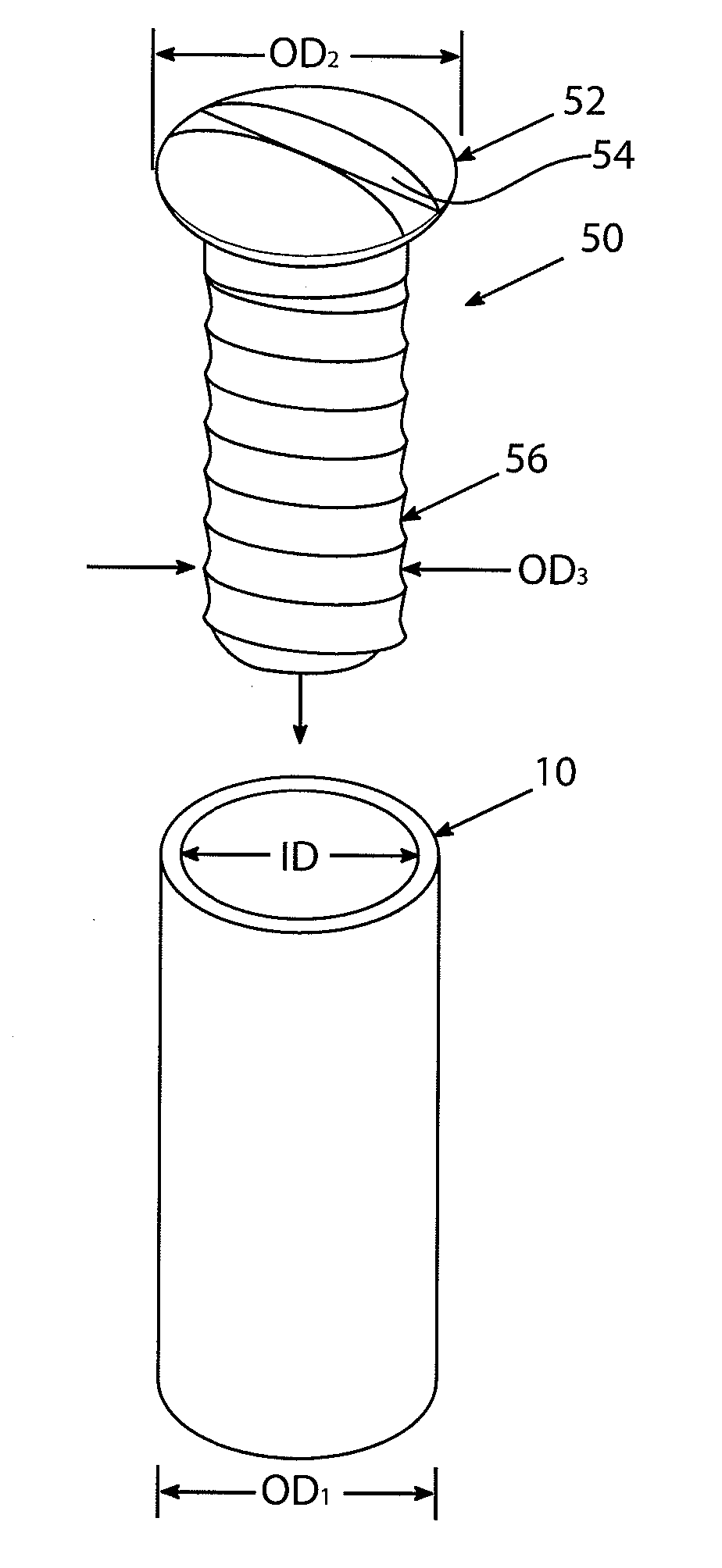
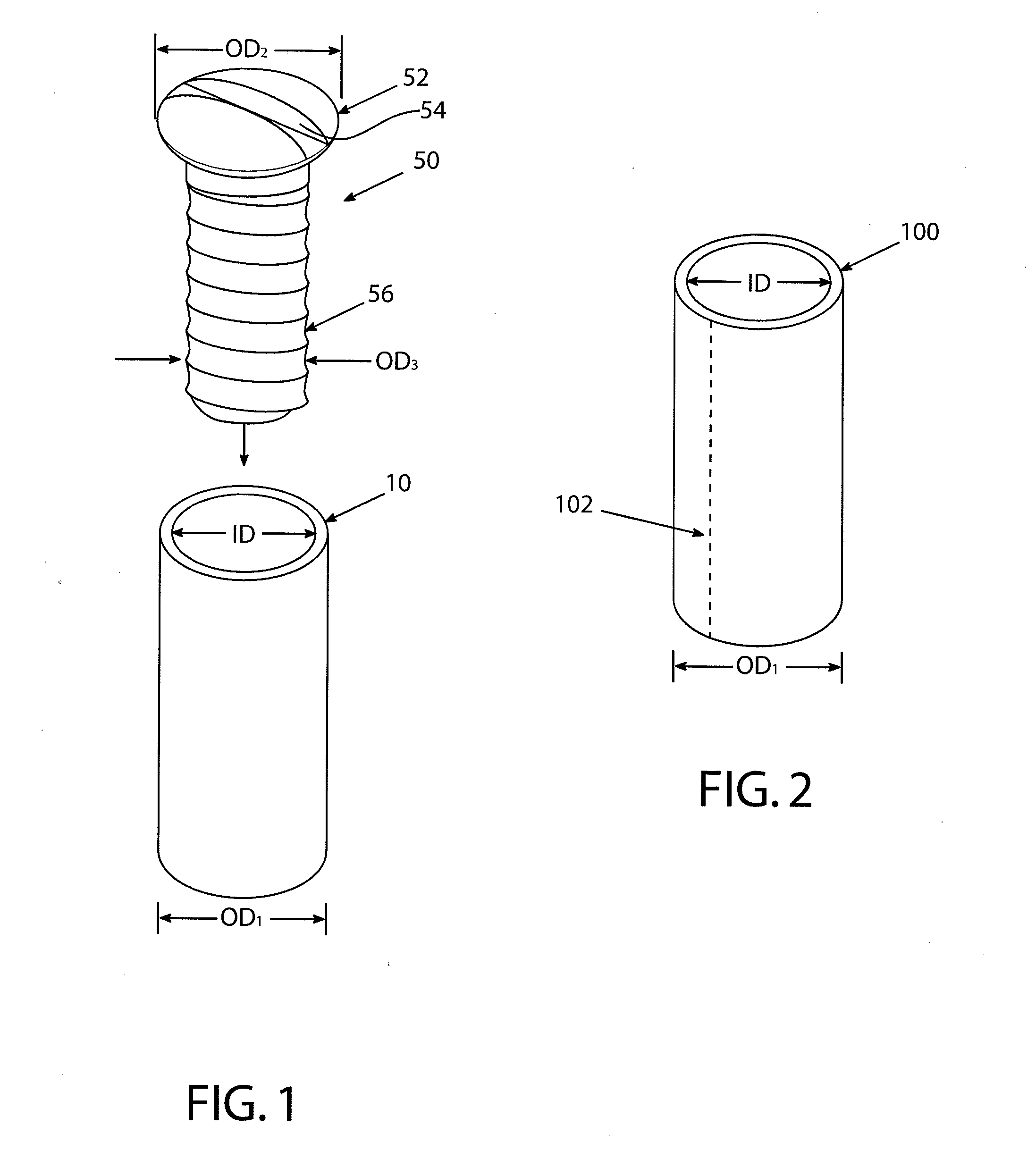
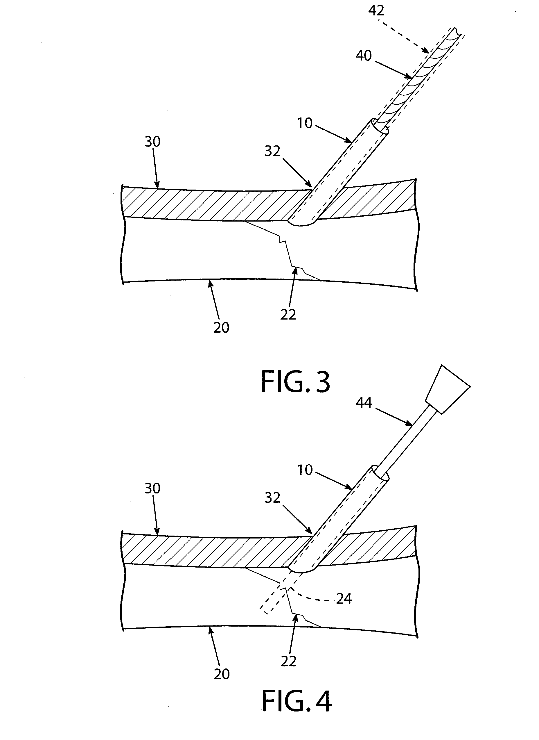
[0023]FIG. 1 depicts a deformable guide sleeve 10 of the present invention, for use in controlled insertion of a surgical screw 50 through an incision and into a hole drilled into a bone of a patient....


PUM


Abstract

A guide sleeve that is deformable or splittable, for use in threading a surgical screw therethrough and into a drilled hole (24) at a surgical site for repair of a fractured bone. The guide sleeve has an inner diameter only as large as the screw shank, not its enlarged head, and the incision need only have a general diameter as large as the guide sleeve outer diameter, causing less trauma and permitting faster healing. A surgical drill may first be inserted through the guide sleeve for drilling the hole through the bone portions traversing the fracture. A surgical screw with enlarged head is then inserted into the guide sleeve to be threaded into the drilled hole, with the enlarged screw head temporarily and locally enlarging the guide sleeve as it passes therethrough until fully threaded into the drilled hole.

Description

CROSS REFERENCE TO RELATED APPLICATIONS[0001]This application is a National Stage entry application of PCT International Patent Application No. PCT / US2011 / 37889 filed May 25, 2011, which claims the priority benefit of U.S. provisional patent application Ser. No. 61 / 348,499 filed May 26, 2010, the contents each of which are incorporated herein by reference in their entirety.FIELD OF THE INVENTION[0002]This relates to the field of medical devices and more particularly to devices for orthopedic surgery.BACKGROUND OF THE INVENTION[0003]Surgical plates and screws are known to be utilized to assist in maintaining the reduction of bone fractures in a patient, thus permitting those fractures to heal in their correct position. Conventionally, in order to place such a screw and / or plate (or, implant) at a selected site, an incision must be made through soft tissue to access the site. These incisions are generally as long as the plate itself. Any soft tissue between the skin and plate / bone mus...

Claims


Application Information

Patent Timeline
Patent Type & Authority Applications(United States)
IPC IPC(8): A61B17/86
CPCA61B17/86A61B17/1735
Inventor FARRELL, ERIC D.
Owner FARRELL ERIC D
Why Eureka
Try Eureka