System and method for determining potential power of inverters during curtailment mode

a technology of curtailment mode and potential power capability, applied in the field of renewable energy sources, can solve the problems of inability to determine the power capability, the amount of power produced by such systems may be unstable, and the inverter is limited by the capacity, so as to achieve the effect of efficient utilization of real and reactive solar power

Active Publication Date: 2013-05-23
GENERAL ELECTRIC CO
View PDF16 Cites 20 Cited by
  • Summary
  • Abstract
  • Description
  • Claims
  • Application Information

AI Technical Summary

Benefits of technology

[0014]transmitting the potential real power capability information received by the controller to a power utility allowing the power utility to more efficiently utilize real and reactive solar power available by the plurality of power inverters.

Problems solved by technology

However, the amount of power produced by such systems may be unstable.
The inverter is limited by the capacity of the power electronics and the renewable energy available at that particular time.
When a solar inverter is operating in curtailed mode, for example, a utility is not able to determine the power capability of the solar inverter, which may change with time due to many factors such as described herein.

Method used


Image

  • System and method for determining potential power of inverters during curtailment mode
  • System and method for determining potential power of inverters during curtailment mode
  • System and method for determining potential power of inverters during curtailment mode

Examples


Embodiment Construction

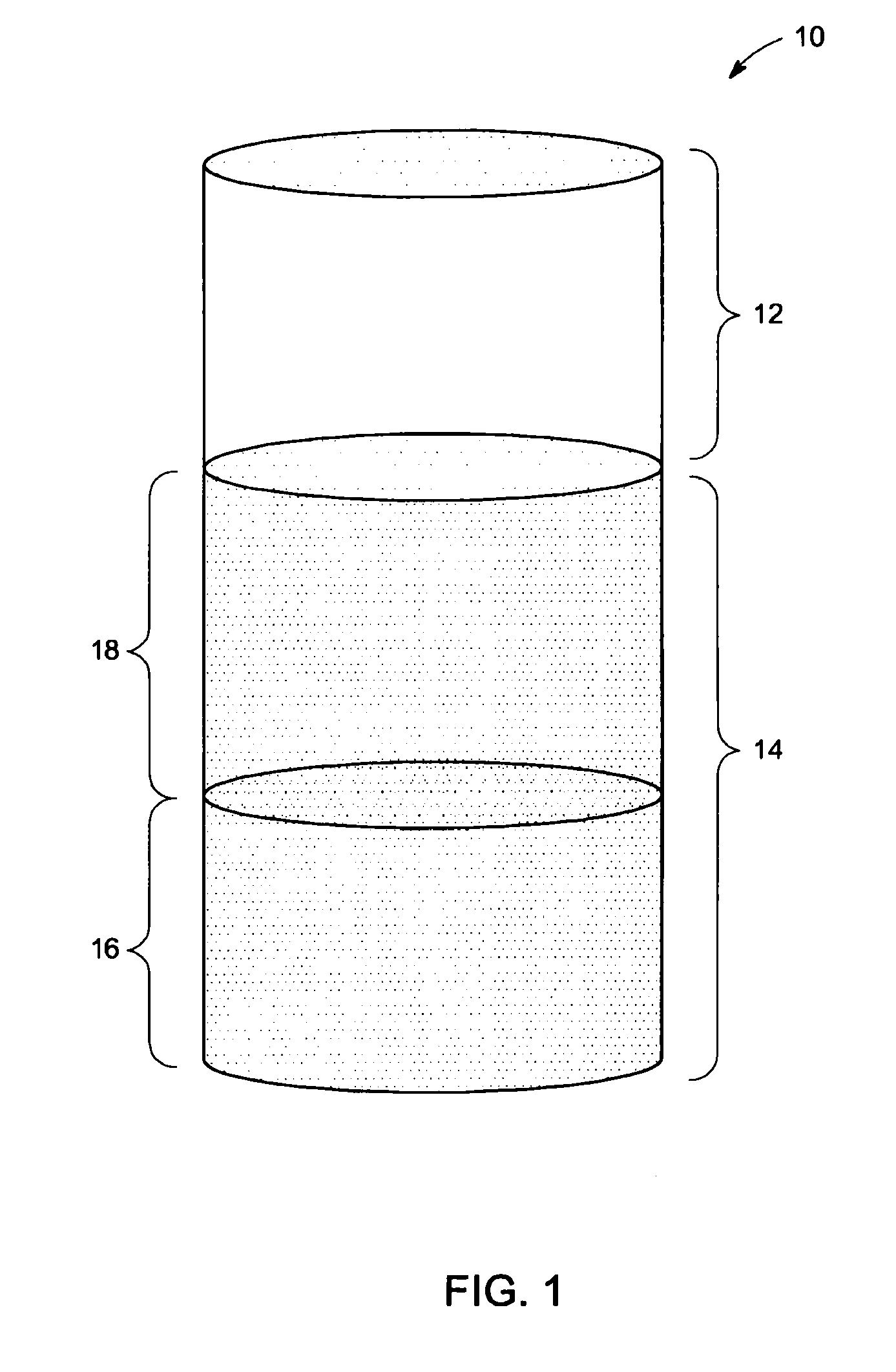
[0022]FIG. 1 illustrates the capacity of a power inverter (10) to support active power (Watts) and reactive power (VARS) according to one embodiment. Power inverter 10 may be part of a solar, wind, battery or hydro power generation system. Assuming power inverter 10 provides power to an electrical grid based on solar power, it can be seen that power inverter 10 has a total power capacity that comprises a reactive power capacity 12 and an active power capacity 14. Power inverter 10 may operate in a curtailed mode of operation as stated herein, in which it generates real or active power 16 that is even less than its true active power capacity 14. Solar inverters are sometimes required to operate in a curtailment mode as also stated herein. Curtailed as used herein means the output is intentionally reduced, by either shutting some inverters down or running all inverters at a reduced rate. A utility operator generally does not know what the plant's full output capability might be. When ...


PUM


Abstract

A power inverter system includes a plurality of power inverters such as solar inverters receiving power from at least one energy source. Each power inverter includes algorithmic maximum peak power tracking (MPPT) software or integrated MPPT firmware to calculate its own potential real power. A controller is in electrical communication with selected power inverters that are operating in curtailed modes of operation and commands each selected power inverter to shift its power production duties and to perform MPPT sweeps. Each selected power inverter then calculates its own potential real power capability in response to corresponding MPPT sweep data. The potential real power capability information is received by the controller that transmits the information to a power utility allowing the power utility to more efficiently utilize real and reactive power available by the plurality of power inverters

Description

BACKGROUND[0001]The subject matter of this disclosure generally relates to renewable energy sources, and more particularly, to systems and methods for determining the potential power capability of power inverters, including but limited to, solar inverters when operating in a curtailment mode.[0002]Solar power generation systems are generally categorized as renewable variable power generation systems because the energy is harvested from naturally occurring and plentiful sources of energy. However, the amount of power produced by such systems may be unstable. The power generated by a solar farm for example, may vary as a function of cloud coverage and the position of the sun in the sky. Such a solar farm may have a plurality of energy harvesting panels with associated photovoltaic cells and inverters that may require power monitoring and control for coordinating and providing power to an electrical grid. For example, a utility may monitor the grid power demand and may need to communic...

Claims


Application Information

Patent Timeline
Patent Type & Authority Applications(United States)
IPC IPC(8): G06F1/28
CPCY02E10/563H02J3/383H02J3/50H02J3/48H02J2300/20H02J2300/26H02J2300/24H02J3/381H02J3/46Y02E10/56
Inventor JAIN, PALAKSCHELENZ, OWEN JANNISO'BRIEN, KATHLEEN ANN
Owner GENERAL ELECTRIC CO
Why Eureka
Try Eureka