Arc Extinction Arrangement and Method for Extinguishing Arcs

a technology of extinction arrangement and extinguishing arcs, which is applied in the direction of electric discharge tubes, instruments, light sources, etc., can solve the problem of extremely low residual energy of arcs in gas discharge chambers, and achieve the effect of simple and cost-effective energy conversion and high arc ra

Active Publication Date: 2013-05-30
HUETTINGER ELECTRONICS GMBH & CO KG
View PDF5 Cites 9 Cited by
  • Summary
  • Abstract
  • Description
  • Claims
  • Application Information

AI Technical Summary

Benefits of technology

[0038]There may be provided a voltage monitoring system which activates the discharging device for discharging the energy store when a predetermined voltage value has been exceeded. The energy store can thereby be protected from excess voltages.
[0039]There may further be provided a voltage monitoring system which deactivates the discharging device for discharging the energy store when a value falls below a predetermined voltage value. The voltage at the energy store can thereby be adjusted in a simple manner. Predeterminable values for arc extinction can consequently be adjusted.
[0040]There may be provided a current monitoring system which activates the discharging device for discharging the energy store when a predetermined current value has been exceeded. The energy store can thereby be protected from excess current.
[0041]There may further be provided a current monitoring system which deactivates the discharging device for discharging the energy store when a value falls below a predetermined current value. The current at the energy store can thereby be adjusted in a simple manner. Predeterminable values for arc extinction can consequently be adjusted.
[0042]The energy removed from the energy store can be converted into heat in the discharging device. Simple and cost-effective energy conversion can thereby be carried out at low arc rates. Energy removed can be at least partially returned to the energy store by means of an energy conversion device of the power supply system connected downstream of the discharging device. Although such an embodiment is slightly more complex, it is energy-saving and space-saving, at least with applications with a high arc rate, in which the conversion of the energy into heat often requires a very large amount of space, since the heat conversion must be distributed over a large surface-area.
[0043]At the switches, a voltage limitation circuit may be provided. It can thereby be ensured that the switches operate to the greatest possible extent in switching mode and the energy is not converted into heat in the switches, but instead is transferred to the energy store. Nonetheless, the switches must be protected from excess voltage.

Problems solved by technology

This leads to a very quick extinction of an arc with extremely low residual energy in the gas discharge chamber.

Method used


Image

  • Arc Extinction Arrangement and Method for Extinguishing Arcs
  • Arc Extinction Arrangement and Method for Extinguishing Arcs
  • Arc Extinction Arrangement and Method for Extinguishing Arcs

Examples


Embodiment Construction

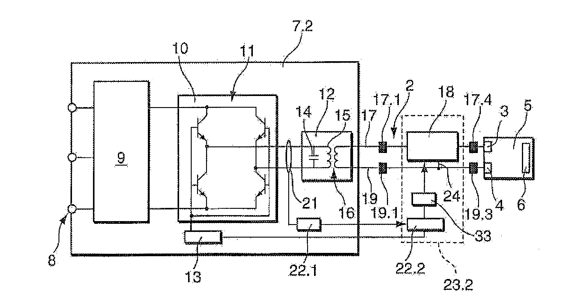
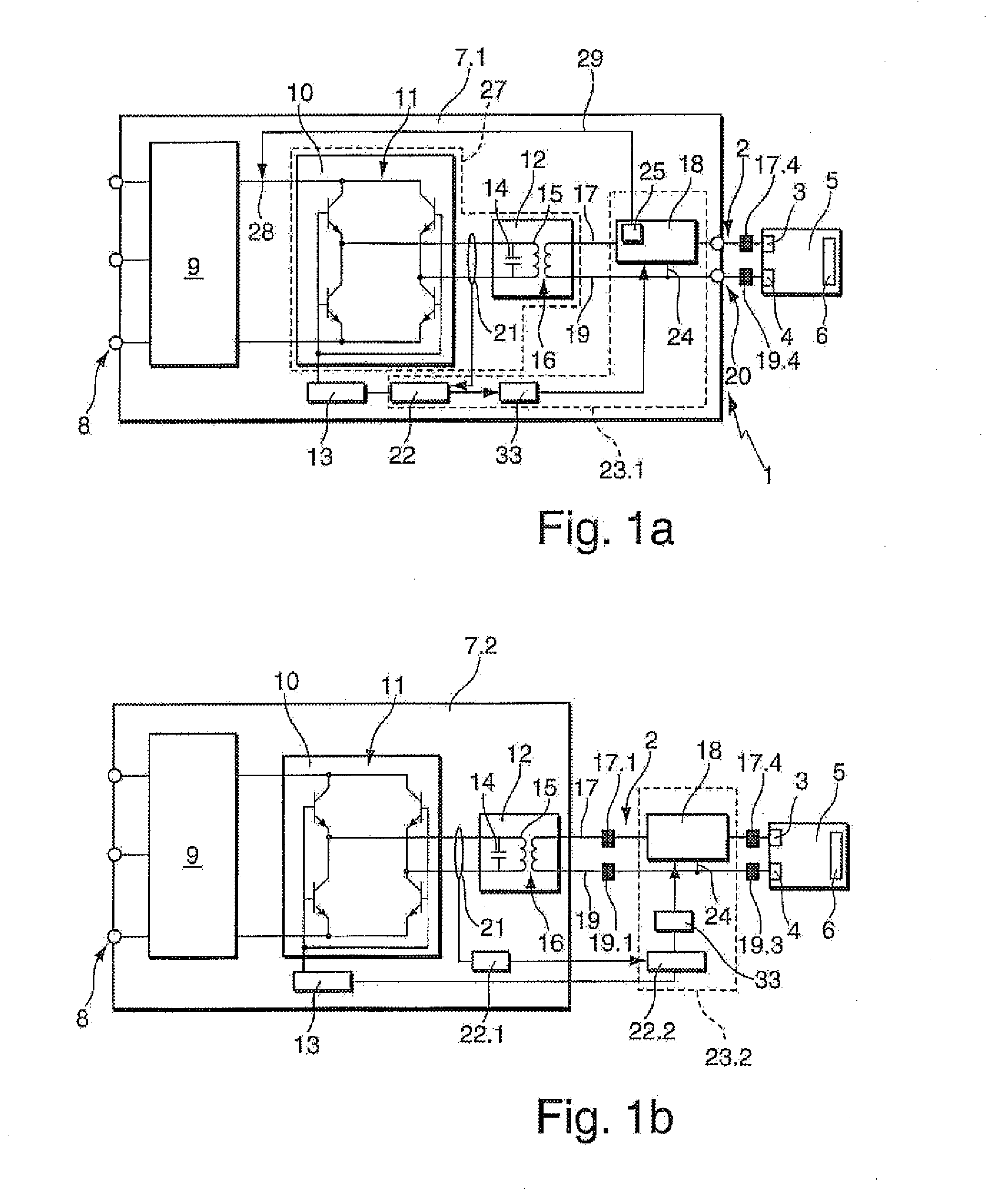
[0053]FIG. 1a illustrates an alternating current voltage gas discharge excitation arrangement 1 which is connected by means of supply lines 2 to electrodes 3, 4 of a gas discharge chamber 5, in particular a plasma installation. The electrodes 3, 4 are arranged in the gas discharge chamber 5 in which a workpiece 6 is processed.

[0054]The alternating current voltage gas discharge excitation arrangement 1 comprises an alternating current voltage generator 7.1 which has a mains connection 8 which may be single-phase or multi-phase. There is connected to the mains connection 8 a mains rectifier 9 which may have other components, such as, for example, a DC / DC converter. At the output thereof is a so-called intermediate circuit direct current voltage. There is connected downstream of the mains rectifier 9 a voltage converter 10 which comprises a bridge circuit 11. An output oscillating circuit 12 is controlled by the voltage converter 10. The output signal of the voltage converter 10 is adj...


PUM


Abstract

In a method for extinguishing an arc in a gas discharge chamber in which power is supplied to a gas discharge chamber and in which both with a current flow in a first direction and with a current flow in a second inverse direction there is produced a gas discharge, when an arc is identified, the power supply to the gas discharge chamber is interrupted, and residual energy which is in a supply line to the gas discharge chamber and/or in the gas discharge chamber is supplied to an energy store.

Description

CROSS REFERENCE TO RELATED APPLICATIONS[0001]This application is a continuation of and claims priority under 35 U.S.C. §120 to PCT Application No. PCT / EP2011 / 059812 filed on Jun. 14, 2011, which claimed priority to German Application No. 10 2010 031 568.0, filed on Jul. 20, 2010. The contents of both of these priority applications are hereby incorporated by reference in their entirety.TECHNICAL FIELD[0002]This specification relates to a method for extinguishing an arc in a gas discharge chamber.BACKGROUND[0003]Vacuum plasma generators are known in various power classes and with various output signal forms.[0004]In vacuum glass coating, for example, medium frequency (MF) generators having an MF output signal with powers between 30 and 300 kW are used. The MF signal is mostly a sinusoidal signal with frequencies between 10 kHz and 200 kHz. The output voltages may be from several 100 V to over 1000 V. In order to ignite the plasma, the voltages are often very much higher than during no...

Claims


Application Information

Patent Timeline
Patent Type & Authority Applications(United States)
IPC IPC(8): H01J37/32
CPCH01J37/32018H01J37/32064H01J37/32935H01J37/32045H01J37/00H01J37/32
Inventor RICHTER, ULRICH
Owner HUETTINGER ELECTRONICS GMBH & CO KG
Why Eureka
Try Eureka