Switching type dc-dc converter for generating a constant output voltage

Active Publication Date: 2006-05-02
ROHM CO LTD
View PDF16 Cites 29 Cited by
  • Summary
  • Abstract
  • Description
  • Claims
  • Application Information

AI Technical Summary

Benefits of technology

[0006]It is therefore an object of the invention to provide a switching type dc-dc converter for providing a predetermined dc voltage by controlling on-off operation of a power transistor receiving an input dc voltage, the converter impl

Problems solved by technology

Although such depending type over-current protection function is usable, the power control transistor of the converter can be destructed by resistive heat generated if a certain constant current continues to flow through it.
As a consequence, although series power supply units can enjoy merits of a fold-back current limiting over-current protection circuit, they are not suitable for use in cases where high power-effici

Method used


Image

  • Switching type dc-dc converter for generating a constant output voltage
  • Switching type dc-dc converter for generating a constant output voltage
  • Switching type dc-dc converter for generating a constant output voltage

Examples


first embodiment

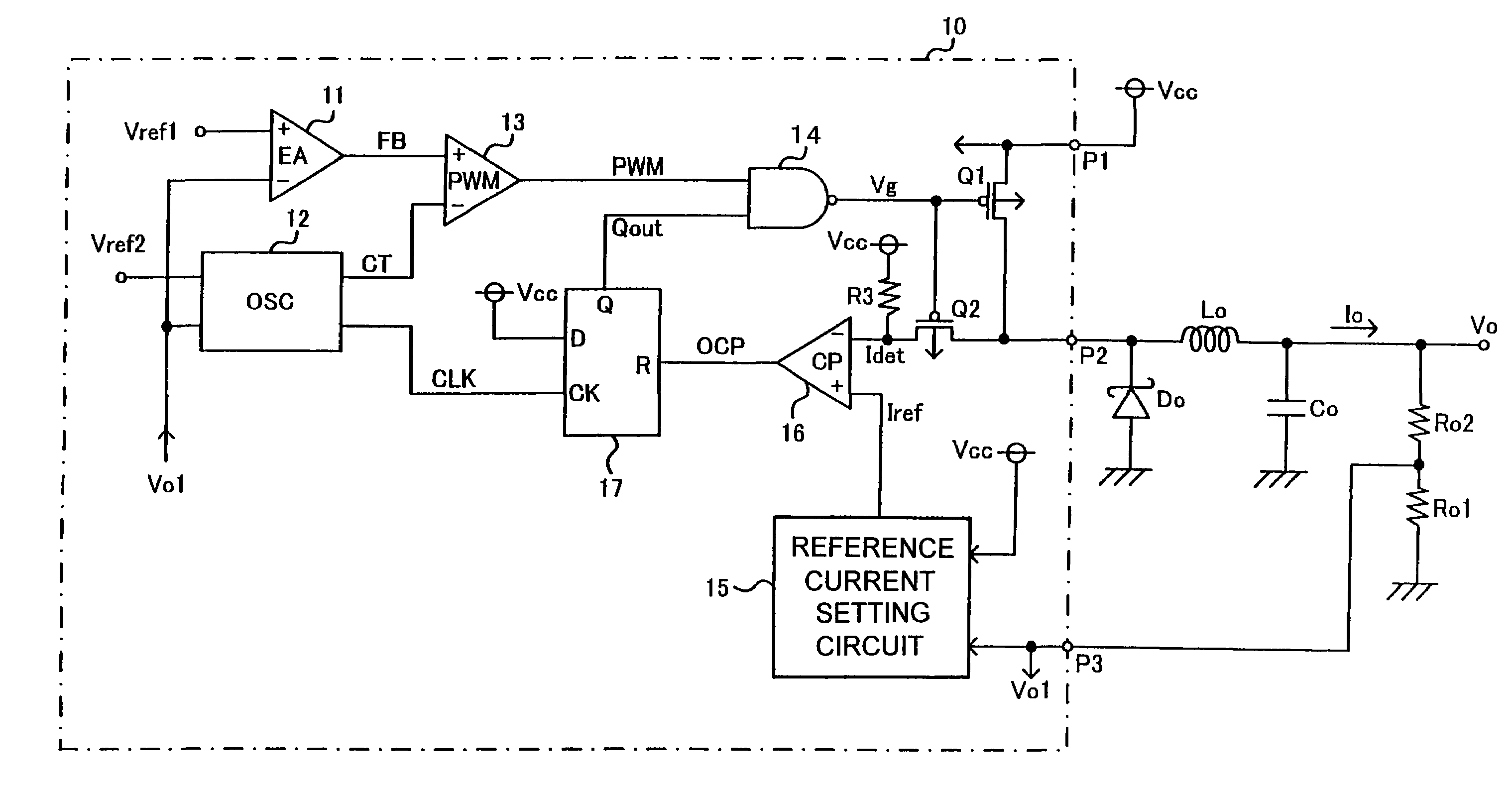
[0032]The invention will now be described by way of example with reference to accompanying drawings. FIG. 1 is a diagram showing the structure of a switching type dc-dc converter in accordance with the invention. FIG. 2 is a diagram showing a specific example of a reference current level setting circuit. FIG. 3 is a diagram showing a specific example of an oscillation circuit. FIG. 4 is a timing diagram illustrating the operation of an inventive dc-dc converter.

[0033]Referring to FIG. 1, there is shown an IC 10 having a first input terminal P1 receiving a dc power supply voltage Vcc. The inputted dc supply voltage Vcc is outputted from the second terminal P2 of the dc-dc converter when a switching transistor Q1 is turned on, but is cut off otherwise, depending on a gate control signal Vg supplied to the gate thereof. The switching transistor Q1 constituting the switching transistor circuit can be a P-type MOS transistor. In what follows, voltages represent potentials relative to the...

second embodiment

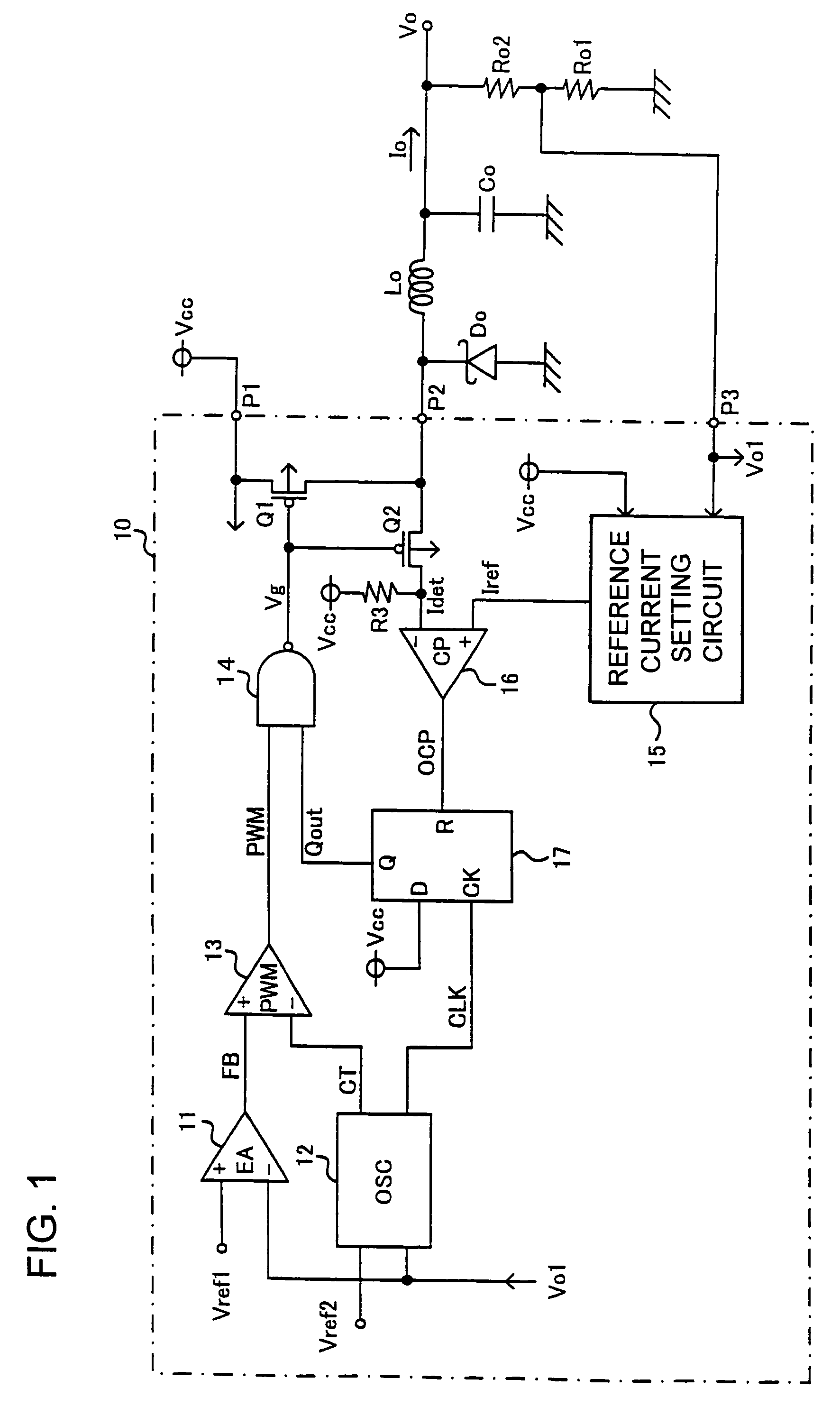
[0071]FIG. 5 shows a configuration of a switching type dc-dc converter in accordance with the invention.

[0072]The reference current level setting circuit 15A of FIG. 5 is adapted to provide a fixed reference current level setting voltage Iref irrespective of the magnitude of the output voltage Vo. Configurations of other components are the same as those of the first embodiment shown in FIG. 1.

[0073]In this example, too, if the output voltage Vo falls down to the predetermined voltage Vref2 during an over-current protective operation, the frequency of the oscillation circuit 12 will be lowered accordingly, thereby reducing the output current Io as desired. As a result of this reduction of the oscillation frequency of the oscillation circuit 12, a characteristic fold-back current limiting scheme is attained during the over-current protective operation.


PUM


Abstract

An inventive switching type dc-dc converter is adapted to set a protective reference current level lower for a decreased output voltage, and stop the switching control signal supplied to a switching transistor circuit when the detected current level exceeds the protective reference current level. In addition, in case where the output voltage declines due to, for example, a circuit failure such as short-circuiting, the switching period of the switching transistor circuit is extended. Thus, the switching type dc-dc converter is provided with a fold-back current limiting type protection characteristic through reduction of the protective reference current level and extension of the switching period of cycle.

Description

FIELD OF THE INVENTION[0001]This invention relates to a switching type dc-dc converter (hereinafter referred to as dc-dc converter) for generating a constant output voltage in a controlled manner, the dc-dc converter equipped with an over-current protection function.BACKGROUND OF THE INVENTION[0002]There have been known many dc power supply units for providing a constant dc voltage by converting an inputted dc voltage, equipped with an over-current protection function to limit the output current to a predetermined level.[0003]An example of such over-current protection function is a depending type protection function in which an output voltage versus output current characteristic for limiting the output current is initiated at a predetermined output current level. Although such depending type over-current protection function is usable, the power control transistor of the converter can be destructed by resistive heat generated if a certain constant current continues to flow through it...

Claims


Application Information

Patent Timeline
IPC IPC(8): G05F1/44G05F1/56H02M3/155H02H9/02H02M3/156H02M3/28
CPCH02M1/32H02M3/156H02M2001/0025H02M1/0025H02M3/28H02H9/02
Inventor GOTO, DAISUKEANDO, HIROAKI
Owner ROHM CO LTD
Why Eureka
Try Eureka