Angular aperture shaped beam system and method

a beam system and beam technology, applied in the field of shaped beams, can solve the problems of increasing the difficulty of achieving beams with sufficient current, increasing the difficulty of achieving single beams that can meet all of these criteria, and excessive time normally needed to mill away all of the material, so as to achieve the effect of more beam curren

Inactive Publication Date: 2005-12-20
FEI CO
View PDF4 Cites 29 Cited by
  • Summary
  • Abstract
  • Description
  • Claims
  • Application Information

AI Technical Summary

Benefits of technology

[0007]The present invention provides improved schemes for generating shaped beam spots having a desired geometric shape using rectangular, elliptical, or semi-elliptical shaped apertures having at least one sharp edge. Depending on the particular beam spot that is desired, combinations of techniques including defocusing, aperture offsetting, stigmation adjustment, and rotation by stigmation can be used in both spherical aberration dominant and chromatic aberration dominant environments to achieve a desired-beam for a desired application. In some cases (e.g., using a semi-circular aperture), the resulting beam has a sharper edge with the same beam current than with conventional shaped beams. In other cases (e.g., with chromatic limited rectangular apertures), the same beam width but with more beam current can be attained.

Problems solved by technology

However, at this point in time these improvements are near their fundamental limits, yet the semiconductor industry and other markets require increased milling throughput and cut quality, particularly for Fab applications.
It is becoming increasingly difficult to achieve beams with sufficient current that are small and thereby sharp enough for precision milling applications using conventional round beams.
Not surprisingly, it is difficult to achieve a single beam that can satisfy all of these criteria.
Even if the beam is small enough to meet sharpness requirements and have adequate resolution for precise, clean cutting, excessive time is normally needed to mill away all of the material because the beam's current is usually fairly small.
However, such systems may not fully address the high current, high current density, and unique density shape requirements for improved milling resolution and throughput desired in many applications.

Method used


Image

  • Angular aperture shaped beam system and method
  • Angular aperture shaped beam system and method
  • Angular aperture shaped beam system and method

Examples


Embodiment Construction

Introduction

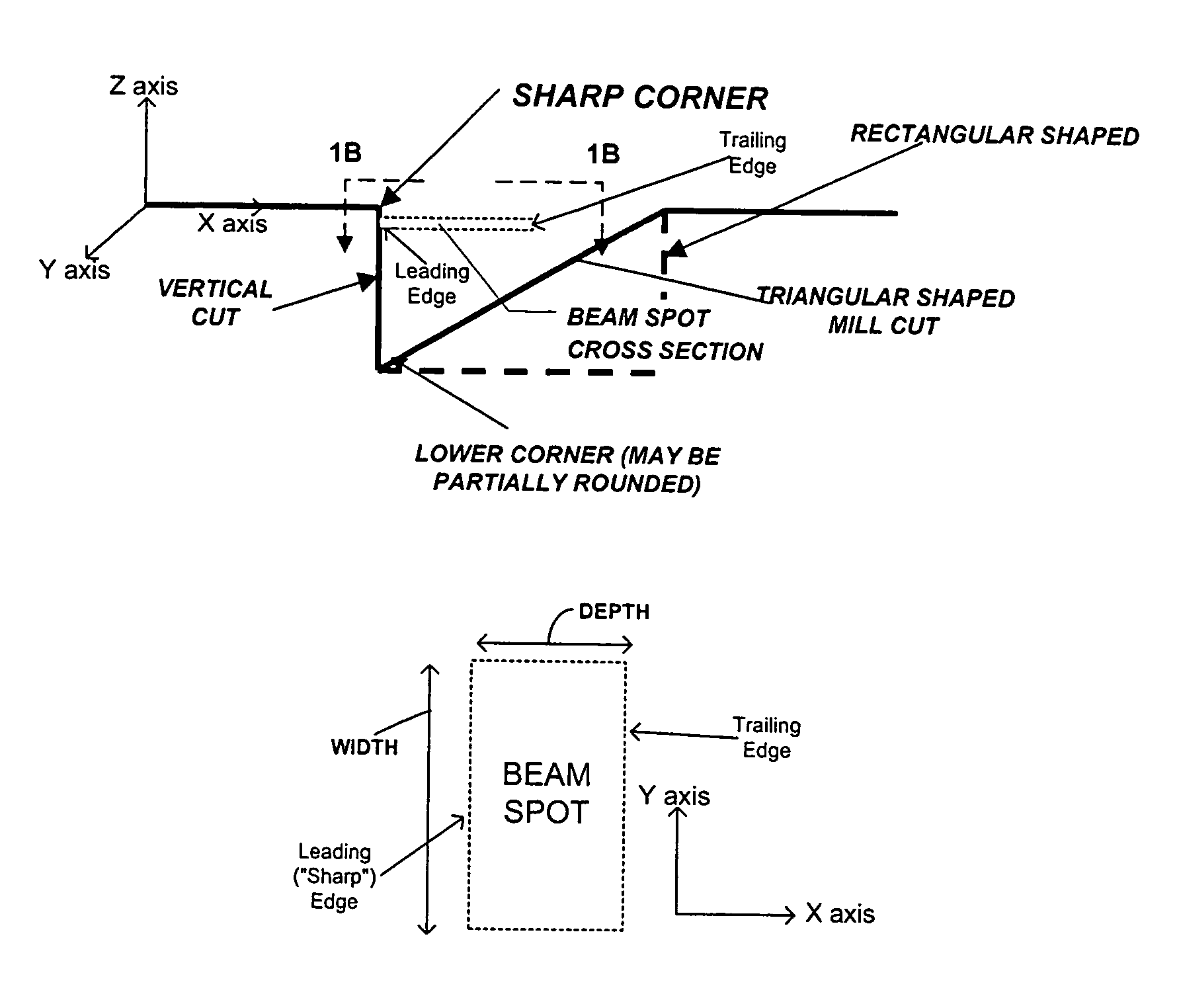
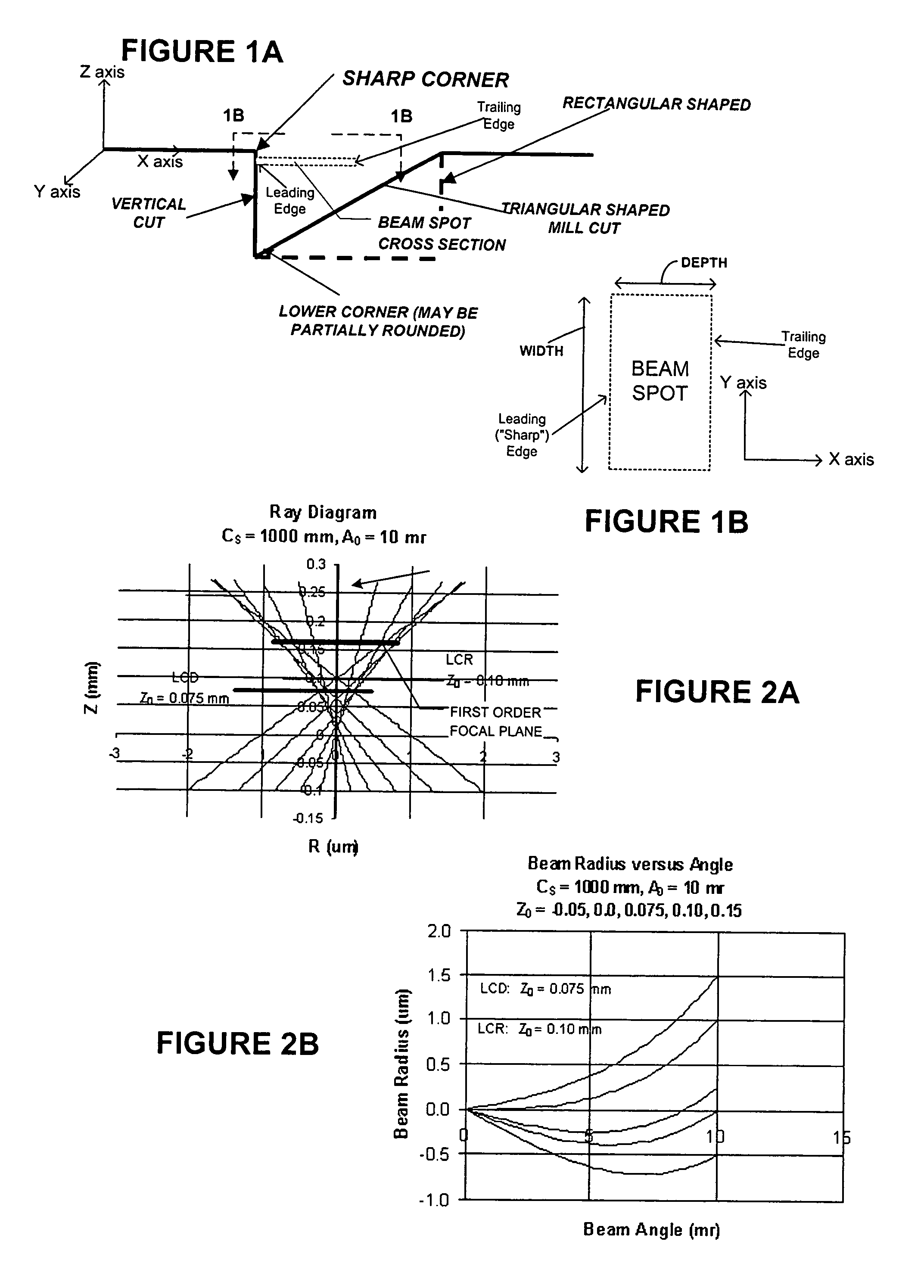
[0029]With reference to FIGS. 1A and 1B, microstructure milling tasks such as cross-sectional cutting for imaging and metallurgical applications require beams with at least one sharp edge for cutting away a slice that leaves a straight, “clean” cross-sectional surface. FIGS. 1A and 1B show a target sample region where such a cross-sectional slice (block or triangular in the depicted figure) is to be cut away using a rectangular shaped beam spot. FIG. 1A is a side view of the beam spot and milling region, while FIG. 1B is a top view of the beam spot taken along lines 1B—1B of FIG. 1A. These figures indicate nomenclature that are used consistently throughout this disclosure.

[0030]The depicted beam spot has a leading edge and a trailing edge. The “leading edge” refers to a straight, sharp edge of the spot that can be used to mill away sharp, vertical surface faces. Conversely, the “trailing edge,” which is on the other side of the spot from the leading edge, usually can hav...


PUM


Abstract

The present invention provides improved angular aperture schemes for generating shaped beam spots having a desired geometric shape from rectangular, elliptical, and semi-elliptical apertures having one sharp edge. A sharper beam edge can be generated by offsetting the rectangular or elliptical aperture in combination with under or over focus. In the spherical aberration limit, under-focused semi-circle apertures provide a sharp, flat edge. The sharp edge can be made resolute enough for precision milling applications, and at the same time, the spot can be made large enough with enough overall current and current density to efficiently mill away material in either a production or laboratory environment. Depending on the particular beam spot that is desired, combinations of techniques including defocusing, aperture offsetting, and stigmation adjustment, can be used in both spherical aberration dominant and chromatic aberration dominant environments to achieve a desired beam for a desired application.

Description

[0001]This application is a continuation-in-part of U.S. patent application Ser. No. 09 / 765,806, filed Jan. 19, 2001.TECHNICAL FIELD OF THE INVENTION[0002]The present invention relates generally to shaped beams. In particular, it relates to shaped beams having a sharp edge or elongated beams having the same width as a round beam but having more beam current.BACKGROUND OF THE INVENTION[0003]Fundamental physics is beginning to limit focused ion beam (“FIB”) performance improvements for round beams. These improvements have arisen primarily from improved electrostatic lens designs and reduced working distances, as well as from the introduction of automated variable apertures. However, at this point in time these improvements are near their fundamental limits, yet the semiconductor industry and other markets require increased milling throughput and cut quality, particularly for Fab applications.[0004]It is becoming increasingly difficult to achieve beams with sufficient current that are ...

Claims


Application Information

Patent Timeline
Patent Type & Authority Patents(United States)
IPC IPC(8): G21K5/04H01J37/09H01J37/153H01J37/30H01J37/305H01J37/31H01J37/317
CPCB82Y10/00H01J37/3007H01J37/3056H01J37/3178H01J2237/045H01J2237/31744H01J2237/31755
Inventor GERLACH, ROBERT L.UTLAUT, MARK W.
Owner FEI CO
Why Eureka
Try Eureka