Real-Time Moving Platform Management System

a real-time moving platform and management system technology, applied in the field of remote sensing/aerial imaging, can solve the problems of not necessarily the case, and the difficulty of determining what people are seeing, and the difficulty of traditional straight down orthogonal ascertaining,

Active Publication Date: 2013-05-30
PICTOMETRY INTERNATIONAL CORPORATION
View PDF11 Cites 22 Cited by
  • Summary
  • Abstract
  • Description
  • Claims
  • Application Information

AI Technical Summary

Benefits of technology

The sensor capture system is designed to receive flight plans in real-time and direct a pilot or control system to fly over a disaster area. It uses small or medium format digital cameras to capture sensor data at altitudes between 2,500 to 10,000 feet, which is sent to a ground station system. The system develops and geo-references the captured data in real-time using a direct registration methodology, allowing for accurate positioning without additional processing. The sensor capture system can manage multiple sensors, providing views of the scene that help first responders quickly recognize what they are looking at and make informed decisions.

Problems solved by technology

However, because the images are captured looking straight down, most people have difficulty determining what they are seeing since people rarely see the world that way.
However, after a disaster occurs, this is not necessarily the case.
This is especially true for hurricanes and floods where the oblique imagery shows the height the water has reached up the sides of buildings—something difficult to ascertain from traditional straight down orthogonal imagery.
While Hurricane Katrina left a large swath of destruction, some areas were more devastated than others.
Satellite image capture systems exist, but while they have the ability to transmit from the sensor to the ground, this does not immediately get the information into the first responders in the field.
First, the satellite cannot loiter over an area, e.g., fly multiple contiguous flight paths—it must maintain its orbit and therefore only comes by a particular geographic region every so often.
Even with the ability to task the sensors on the satellite that generally only widens the window of opportunity over the target or increases the frequency over the target—it still does not allow it to loiter about a predetermined ground area.
Second, even if a satellite image capture system could loiter, because satellites fly so high over the earth, any cloud cover will obstruct their view of the ground.
Since there is typically a lot of cloud cover after weather related disasters, such as hurricanes, floods, and tornadoes, this presents a serious problem, further compounded by the satellites inability to loiter.
Third, many satellites download the data in a batch format when they are passing over an appropriate receiving station, rather than downloading images in real-time to a van or other ground station on site at the emergency response center.
Fourth, most satellite data requires significant post-processing in order to put the images into a form that can be readily understood or used by the Geospatial Information Systems (GIS) and Computer Aided Dispatch (CAD) systems the first responders use during emergency response.
Traditional aerial image fliers do not provide the captured data directly into the hands of the first responders in the field in real-time for a variety of reasons.
First, the data rates off the sensor are generally prohibitive for successfully transmitting data to the ground in real-time.
Third, there was no known and available direct download systems in the industry capable of reliably downloading the data from the airplane to the ground.
However, this is often impractical or unreliable for communicating with a communication system carried by an airplane used to capture images with the aid of a flight plan in response to a disaster and which may be travelling more than 25 miles away from the dish antenna.
Further, the conventional methodologies did not provide an automated method for reestablishing a connection or data synchronization problems after a drop-out of the high speed link.

Method used


Image

  • Real-Time Moving Platform Management System
  • Real-Time Moving Platform Management System
  • Real-Time Moving Platform Management System

Examples


Embodiment Construction

[0058]Before explaining at least one embodiment of the invention in detail, it is to be understood that the invention is not limited in its application to the details of construction, experiments, exemplary data, and / or the arrangement of the components set forth in the following description or illustrated in the drawings. The invention is capable of other embodiments or being practiced or carried out in various ways. Also, it is to be understood that the phraseology and terminology employed herein is for purposes of description and should not be regarded as limiting.

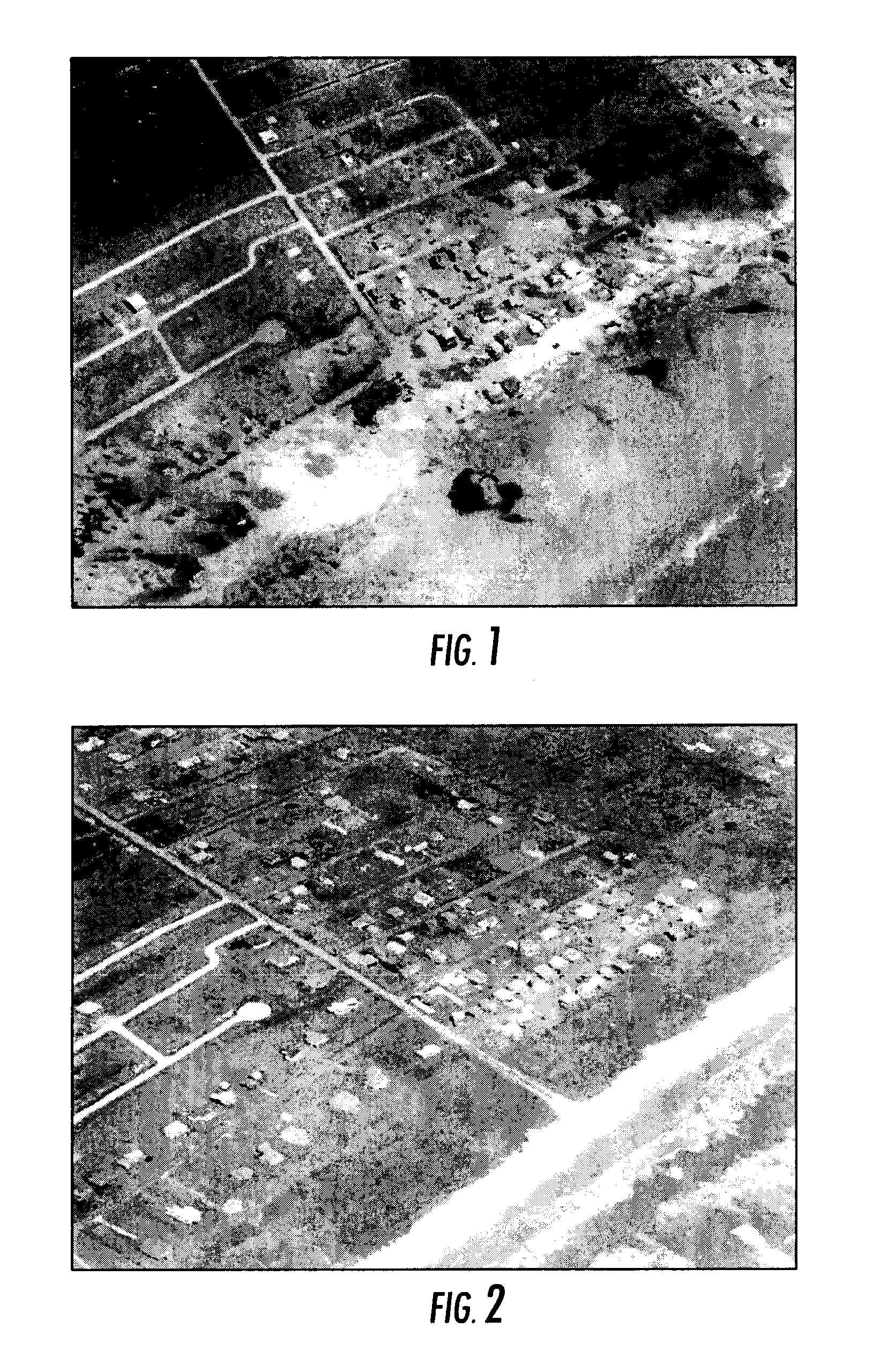
[0059]Referring now to the drawings, FIGS. 1 and 2 are oblique images showing footage of a portion of the coastline in Galveston Tex. before and after Hurricane Ike. As shown in FIG. 1, the damage to Galveston Tex. was extensive and the Federal Emergency Management Agency was deployed immediately to the region in an emergency response effort.

[0060]In disasters, emergency response teams need to be provided with critical ...


PUM


Abstract

The present disclosure describes a method for creating data products in real-time with the aid of a ground station system. The method includes the steps of monitoring one or more communication links for newly captured sensor data and positional data of oblique images, saving the sensor data and positional data to one or more directories of one or more computer readable media, monitoring the one or more directories of one or more computer readable media for sensor data and positional data, processing the sensor data and positional data to create one or more data products for use by one or more mapping and exploitation systems responsive to the sensor data and positional data being saved in the one or more directories, and storing the one or more data products to one or more directories of one or more computer readable media.

Description

CROSS-REFERENCE TO RELATED APPLICATIONS[0001]The present patent application hereby incorporates by reference the patent application identified by U.S. Ser. No. 12 / 831,971 , which was filed on Jul. 7, 2010 and titled “Real-time Moving Platform Management System.”STATEMENT REGARDING FEDERALLY SPONSORED RESEARCH AND DEVELOPMENT[0002]This invention was made with government support under SBIR / STTR topic number H-SB06.1-006 and / or contract number NBCH080046 awarded by the Department of Homeland Security Advanced Research Projects Agency. The government has certain rights in the invention.BACKGROUND OF THE INVENTION[0003]As background, in the remote sensing / aerial imaging industry, imagery is used to capture views of a geographic area and to be able to measure objects and structures within the images as well as to be able to determine geographic locations of points within the image. These are generally referred to as “geo-referenced images” and come in two basic categories:[0004]Captured I...

Claims


Application Information

Patent Timeline
Patent Type & Authority Applications(United States)
IPC IPC(8): H04N7/00G01S17/89
CPCG01C11/02G01S17/89G06T17/05H04N7/18G09G5/377H04N7/005H04N7/181H04B7/18506H04B7/18508H04W4/027H04W4/40
Inventor GIUFFRIDA, FRANK D.WINKELBAUER, MARK A.MONDELLO, CHARLESBRADACS, ROBERT S.WOODWARD, CRAIG D.SCHULTZ, STEPHEN L.
Owner PICTOMETRY INTERNATIONAL CORPORATION
Why Eureka
Try Eureka