Light reflecting member, light beam extension device, image display device, and optical device

a technology of image display device and light beam extension, which is applied in the direction of mirrors, instruments, mountings, etc., can solve the problems described below and achieve the effects of reducing the size, reducing the weight of the image display device, and no degradation of display contras

Inactive Publication Date: 2013-05-30
SONY CORP
View PDF1 Cites 65 Cited by
  • Summary
  • Abstract
  • Description
  • Claims
  • Application Information

AI Technical Summary

Benefits of technology

[0085]In the image display devices according to the first to fourth embodiments of the present disclosure, the optical devices according to the first and second embodiments of the present disclosure, or the light beam extension device according to the first and second embodiments of the present disclosure, the light beam extension device which extends a light beam (luminous flux) along the Z direction and makes the light beam be incident on the light guide unit is provided. Therefore, it is not necessary to set the diameter in the Z direction of an aperture stop in the image generating device to be large and it is not necessary to make the diameter of a lens to be provided in the image generating device large, and thus a reduction in the size and a reduction in the weight of the image display device can be attained and there is also no degradation in display contrast and deterioration in image quality. Further, in the image display devices according to the first to fourth embodiments of the present disclosure, the optical devices according to the first and second embodiments of the present disclosure, the light beam extension device according to the first and second embodiments of the present disclosure, or the light reflecting members according to the first and second embodiments of the present disclosure, since various parameters in the slope of the light reflecting surface or the light reflecting member are defined, light incident on the light beam extension device or the light reflecting member can be efficiently emitted.

Problems solved by technology

On the other hand, in such a configuration, since a propagation distance of light which is guided in the inside of the light guide plate 1131 becomes relatively long, problems described below arise.

Method used


Image

  • Light reflecting member, light beam extension device, image display device, and optical device
  • Light reflecting member, light beam extension device, image display device, and optical device
  • Light reflecting member, light beam extension device, image display device, and optical device

Examples


example 1

[0231]Example 1 relates to the light reflecting member according to the first embodiment of the present disclosure, the optical device according to the first embodiment of the present disclosure, the light beam extension device according to the first embodiment of the present disclosure, and the image display device according to the first embodiment of the present disclosure.

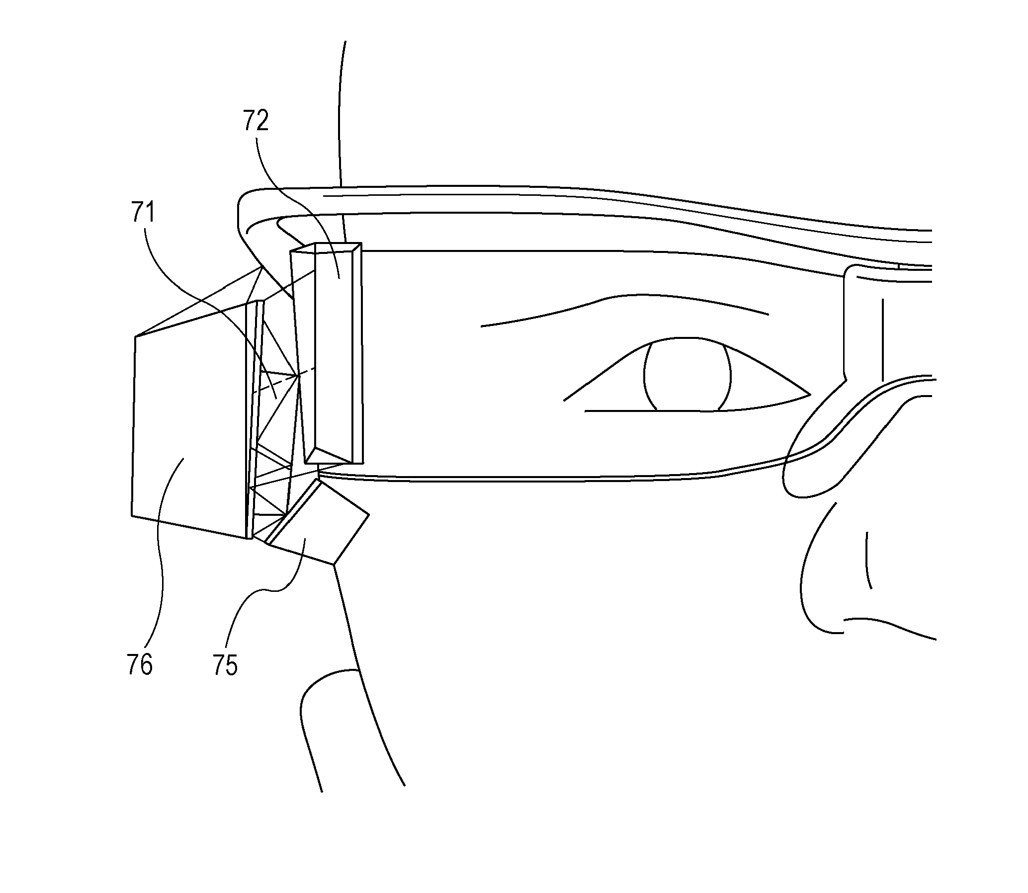
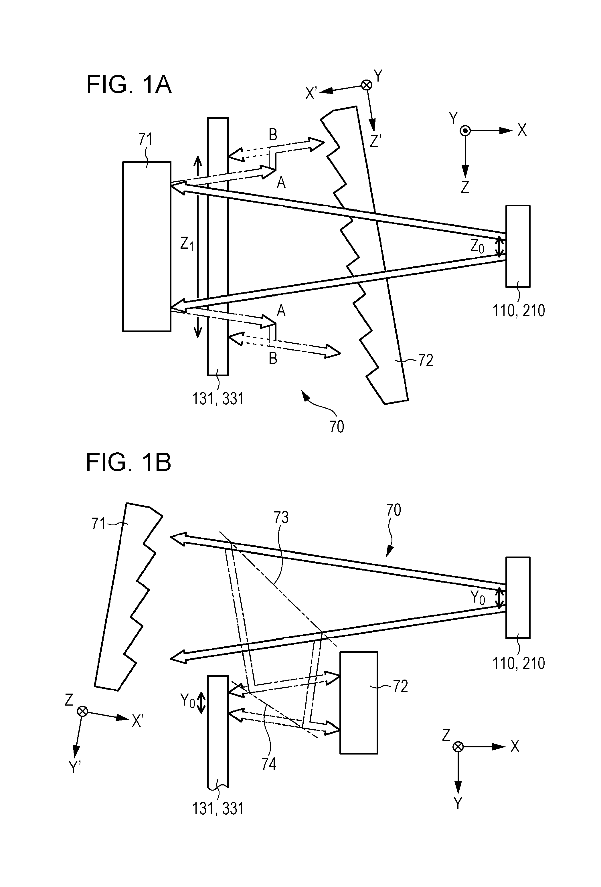
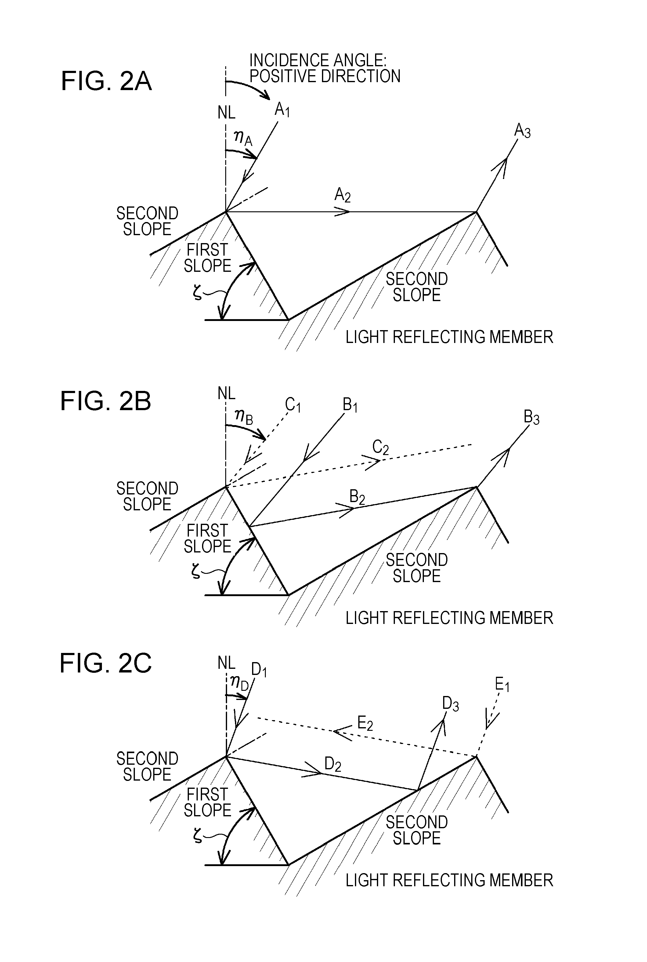
[0232]Conceptual diagrams when the light beam extension device of Example 1 is viewed from the Y direction and the Z direction are illustrated in FIGS. 1A and 1B, and the behavior of incident light and emitted light in the light reflecting member is illustrated in FIGS. 2A to 2C. Further, a schematic partial cross-sectional view of a first reflecting mirror when the first reflecting mirror is cut in a first A imaginary plane that is an imaginary plane orthogonal to the Z direction, a schematic partial plan view of the first reflecting mirror, and a schematic partial side view (however, only the behavior of light...

example 2

[0281]Example 2 is a modification of Example 1 and relates to the image generating device 210 of the second form. The image display device 200 or 400 of Example 2 or Example 4 (described later) includes, as illustrated as a conceptual diagram in FIG. 22 or 24,

[0282](A-1) the light source 261,

[0283](A-2) a collimating optical system 262 which turns light emitted from the light source 261 into collimated light,

[0284](A-3) a scanning unit 263 which performs scanning with the collimated light emitted from the collimating optical system 262, and

[0285](A-4) a relay optical system 264 which relays the collimated light irradiated from the scanning unit 263, and

[0286]light from the relay optical system 264 is incident on the first reflecting mirror 71.

[0287]Here, since the light guide unit 130 has the same configuration and structure as those of the light guide unit 130 described in Example 1, detailed description is omitted.

[0288]The light source 261 includes a red light-emitting element 26...

example 3

[0289]Example 3 is also a modification of Example 1. As illustrated as a conceptual diagram in FIG. 23A, the image forming device 111, the collimating optical system 112, and the light beam extension device 70 in the image display device 300 of Example 3 have the same configurations and structures as those of the image forming device 111, the collimating optical system 112, and the light beam extension device 70 described in Example 1. Further, the light guide unit 330 is also equal in the following basic configuration and structure to the light guide unit 130 of Example 1 except that the configurations and structures of the first deflection section and the second deflection section are different from those in Example. That is, the light guide unit 330 is equal to the light guide unit 130 of Example 1 in that the light guide unit 330 includes

[0290](C-1) the light guide plate 331 in which incident light is propagated by total reflection in the inside and then emitted therefrom,

[0291]...


PUM


Abstract

An image display device includes an image generating device, a light guide unit which includes a light guide plate and first and second deflection sections, and a light beam extension device which extends light incident from the image generating device, along a Z direction when an incident direction of light incident on the light guide plate is set to be an X direction and a direction of propagation of light in the light guide plate is set to be a Y direction, and emits the light to the light guide unit, wherein the light beam extension device includes a first reflecting mirror on which light from the image generating device is incident, and a second reflecting mirror which emits light incident from the first reflecting mirror to the light guide unit, and each of the first and second reflecting mirrors has a light reflecting surface having a sawtooth-shaped cross-sectional shape.

Description

BACKGROUND[0001]The present disclosure relates to a light reflecting member, a light beam extension device with the light reflecting member incorporated therein, an optical device with the light beam extension device incorporated therein, and an image display device with the optical device incorporated therein.[0002]A virtual image display device (an image display device) for making an observer observe a virtual image made by enlarging a two-dimensional image formed by an image forming device by a virtual image optical system is disclosed in, for example, Japanese Unexamined Patent Application Publication (Translation of PCT Application) No. 2005-521099 or Japanese Unexamined Patent Application Publication No. 2006-162767.[0003]As illustrated as a conceptual diagram in FIG. 40, an image display device 1000 includes an image forming device 1011 having a plurality of pixels arranged in the form of a two-dimensional matrix, a collimating optical system 1012 which turns light emitted fr...

Claims


Application Information

Patent Timeline
Patent Type & Authority Applications(United States)
IPC IPC(8): G02B27/01G02B17/02G02B17/00F21V8/00
CPCG02B27/0101G02B6/0031G02B17/02G02B27/0172G02B6/0018G02B2027/0125G02B17/006
Inventor AKUTSU, KATSUYUKIAKAO, HIROTAKA
Owner SONY CORP
Why Eureka
Try Eureka