Flight control laws for automatic hover hold

a technology of automatic hover hold and control laws, applied in the field of flight control systems, can solve the problems of significant flight safety risks, paramedics, patient's mother, flight nurse,

a technology of automatic hover hold and control laws, applied in the field of flight control systems, can solve the problems of significant flight safety risks, paramedics, patient's mother, flight nurse,

US20130138270A1Active Publication Date: 2013-05-30TEXTRON INNOVATIONS

Image

  • Flight control laws for automatic hover hold
  • Flight control laws for automatic hover hold
  • Flight control laws for automatic hover hold

Examples


Embodiment Construction

[0025]The present application is directed to existing aircraft sensors, actuators, and control laws to help the pilot overcome brownout or degraded visual environment (DVE) flight. The innovative control law architecture, with advanced concepts to stabilize the aircraft, allows the pilot to maneuver at low speed with minimal compensation and workload. It has been demonstrated in previous flight testing that even with wind conditions as high as 30-35 knots, aircraft performance will not degrade with the advanced control laws (CLAWS) of the present application. More than 80 hours of flight testing have been conducted to prove the robustness of these CLAWS. Furthermore, it has been shown that even non-pilots can handle the aircraft utilizing the CLAWS of the present application.

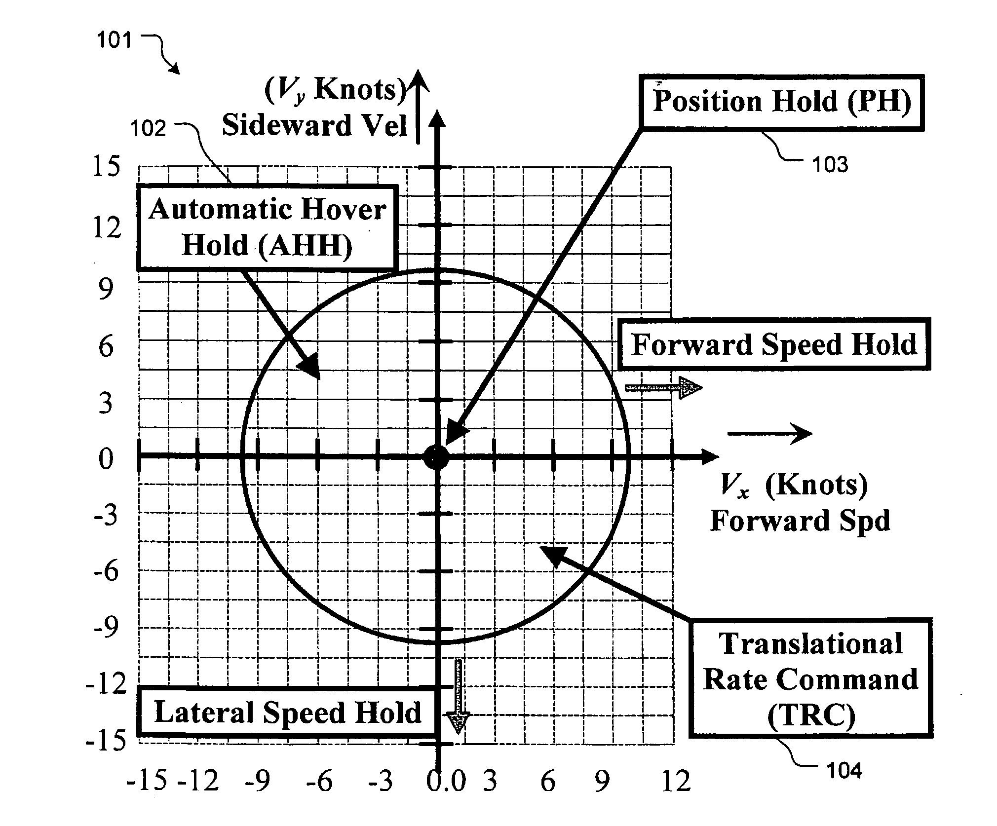
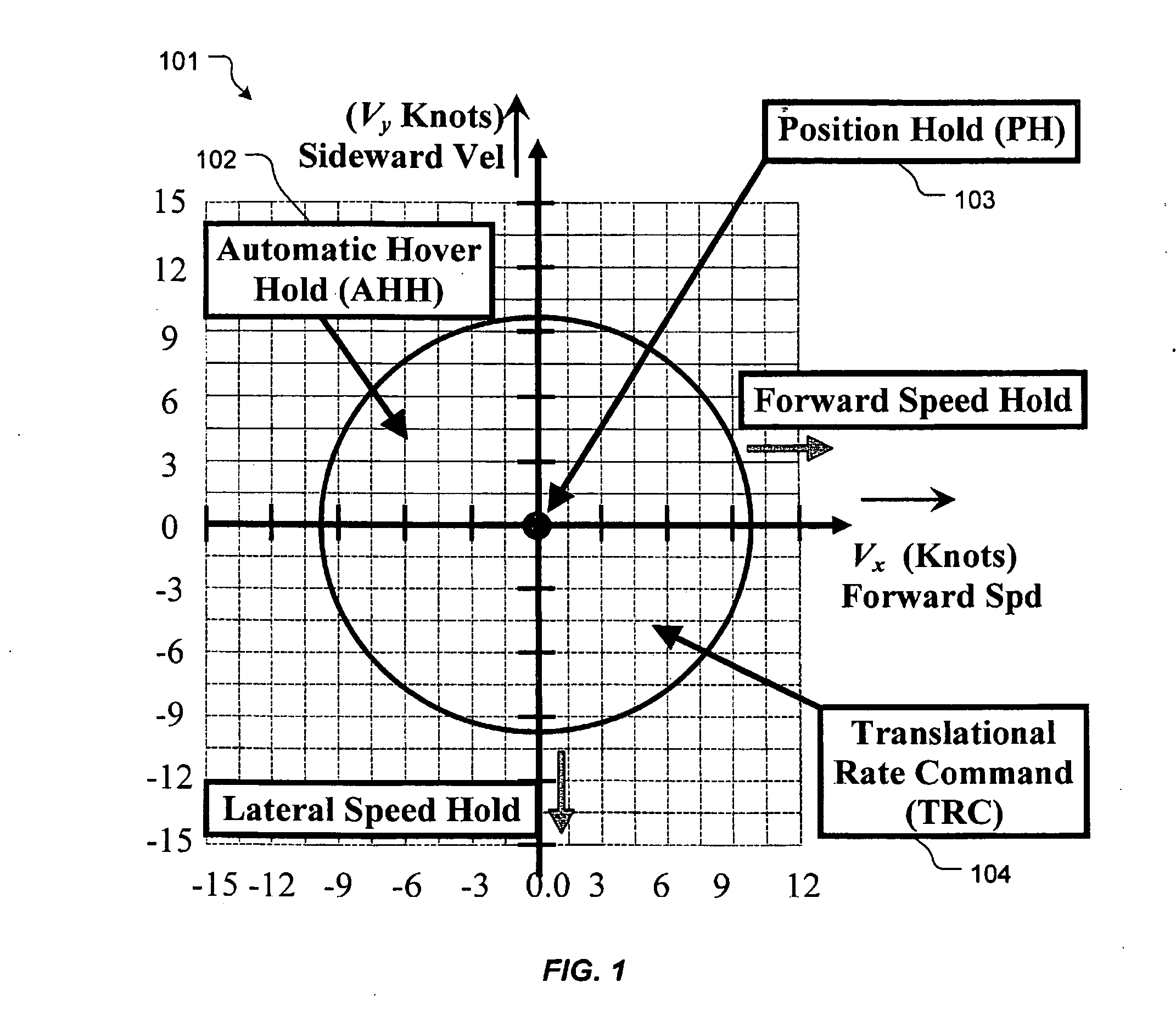
[0026]Referring now to FIG. 1 in the drawings, various flight envelopes are depicted in chart 101. Automatic hover hold (AHH) 102 will engage if the pilot releases both the longitudinal and lateral controls when...


PUM


Abstract

A system and method to control hovering flight of a rotary aircraft. The system including a lateral speed hold loop, a longitudinal loop, a vertical control loop, and a directional loop. The method includes defining a first flight envelope having a first groundspeed threshold; defining a second flight envelope having a second groundspeed threshold, the second flight envelope being defined within the first envelope; engaging a hover hold with a control law hover hold architecture as the aircraft enters the first flight envelope; and engaging a position hold with a control law position hold architecture as the aircraft enters the second flight envelope.

Description

TECHNICAL FIELD[0001]The present application relates generally to flight control systems, and more particularly, to flight control laws for automatic hover hold.DESCRIPTION OF THE PRIOR ART[0002]Brownout or whiteout is a phenomenon where flight visibility is reduced due to airborne particles from rotor downwash. During brownout, the pilot is unable to see nearby objects which are necessary to provide outside visual references in order to control the aircraft while hovering near the ground. Because of brownout, the degraded visual environment can cause the pilot to lose awareness, which can lead to an accident.[0003]Brownout during helicopter landing and take-off operations in arid desert terrain has been responsible for more than 30 accidents in recent years. Intense, blinding dust clouds stirred up by the helicopter rotor downwash can cause significant flight safety risks from ground obstacle collisions and dynamic rollover due to uneven terrain.[0004]In 2004, an emergency medical ...

Claims


Application Information

Patent Timeline
30 May 2013
Publication
US20130138270A1
IPC
B64C19/00
CPC
G05D1/102; B64C19/00
Inventors
CHRISTENSEN, KEVIN THOMAS; SHUE, SHYHPYNG JACK