

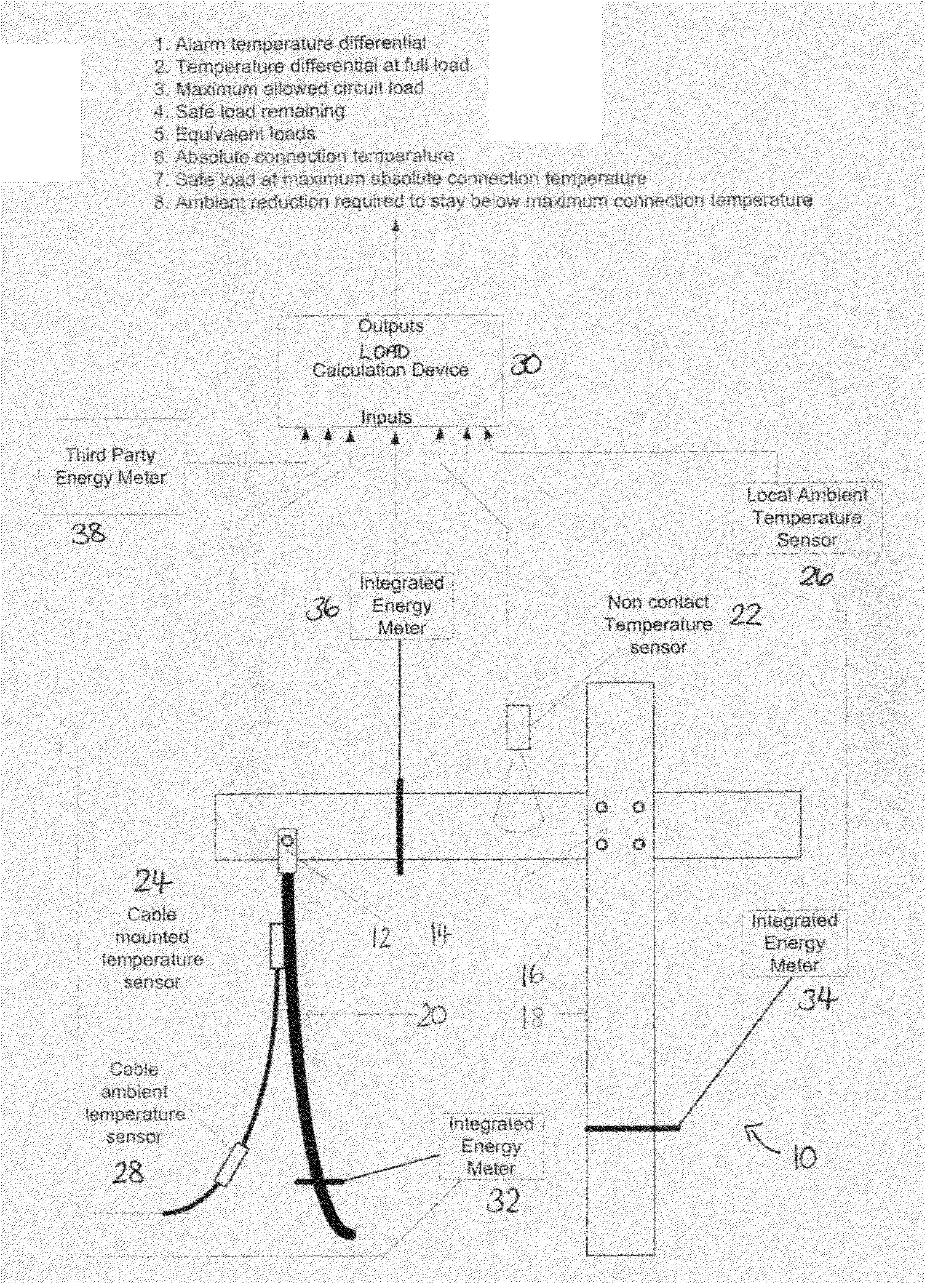
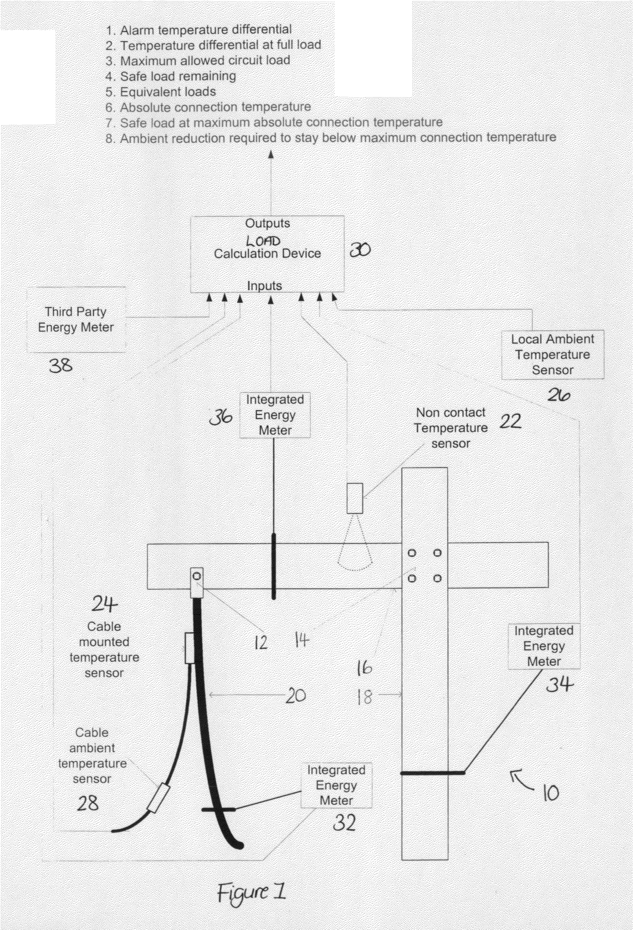
Dynamic Thermal Mapping
a thermal mapping and dynamic technology, applied in the direction of electrical equipment construction details, power measurement by current/voltage, instruments, etc., can solve the problems of arc flash, severe damage to electrical equipment, and fatal injury to anyone in close proximity to the compromised electrical joint, so as to achieve the maximum safe operating capacity of the electrical circuit
- Summary
- Abstract
- Description
- Claims
- Application Information
AI Technical Summary
Benefits of technology
Problems solved by technology
Method used
Image

Examples
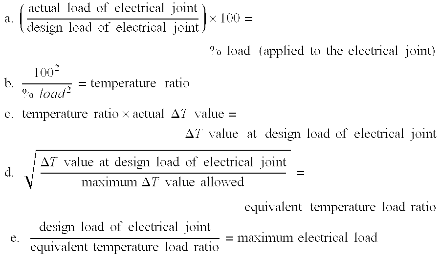
example 1
[0195]Actual electrical joint load=201 Amps
[0196]Design electrical joint load=619 Amps
[0197]Actual ΔT=4.5° C.
[0198]Maximum ΔT=40° C.
(201619)×100=32.47%100232.472=100001054.30=9.489.48×4.5°C.=42.66°C.42.6640.00=1.036191.03=600.97Ampsmaximumload600.97-201=399.97AmpsremainingbeforetheelectricaljointandthustheelectricalcircuitexceedsmaximumallowedΔTvalueof40°C.
[0199]The load calculation device would therefore calculate in real time:[0200]maximum electrical load of 600.97 Amps that the electrical joint and thus the electrical circuit can safely handle;[0201]remaining load of 399.97 Amps that we can expect the electrical joint and thus the electrical circuit to safely handle;[0202]ΔT value of 42.66° C. that the electrical joint will reach if allowed to run at the design load of the electrical circuit, and thus the design load of the electrical joint.
[0203]The load calculation device provides to the operator in real time;[0204]current ΔT value that the electrical joint is operating at in °...
example 2
[0216]Actual circuit load=201 Amps
[0217]Design circuit load=619 Amps
[0218]Actual ΔT=6.0° C.
[0219]Ambient temperature=35° C.
(201619)×100=32.47%100232.472=100001054.30=9.489.48×6.0°C.=56.88°C.56.88°C.+35.00°C.=91.88°C.(actualjointtemperature)91.8885.00=1.046191.04=595.19Ampsmaximumelectricalload595.19-201=394.19Ampsremainingbeforecircuitexceedsmaximumallowedconductortemperatureof85°C.
[0220]The load calculation device would therefore calculate in real time:[0221]maximum electrical load of 595.19 Amps that the circuit can safely handle;[0222]remaining load of 394.19 Amps that we can expect the circuit to safely handle;[0223]an actual temperature of the electrical joint of 91.88° C. that the electrical joint will reach if allowed to run at the design circuit load.
[0224]The load calculation device then subtracts the maximum allowed electrical conductor temperature from the actual conductor temperature, i.e. 85.0° C.-91.88° C., to provide the value that the ambient temperature needs to be ...
example 3
[0239]For a maximum allowed ΔT value of 40° the ΔT value threshold at 40% electrical load is calculated as follows:
40×(40100)2=6.4°C.ΔTvaluethreshold
[0240]The load calculation device provides to the operator continuously in real time;[0241]current ΔT value that the electrical joint is operating at in ° C. or ° F.;[0242]design load of the electrical circuit and thus the electrical joint in Amps;[0243]actual electrical load applied to the electrical circuit and thus the electrical joint in Amps;[0244]ΔT value alarm threshold for the % electrical load utilized on the circuit in ° C. or ° F., equivalent to that which would apply at 100% electrical load.
along with other interactive capabilities.
PUM
 Abstract
Description
Claims
Application Information