Rotary valve adapter assembly with planetary gear system

a technology of planetary gear system and adapter assembly, which is applied in the direction of valve details, valve arrangement, valve operating means/release devices, etc., can solve the problems of insufficient force transmitted by the magnets to ensure the proper function of the valve, difficult to transmit adequate force to the valve stem, and not giving the valve operator the confidence that his valve can be opened or closed

a technology of planetary gear system and adapter assembly, which is applied in the direction of valve details, valve arrangement, valve operating means/release devices, etc., can solve the problems of insufficient force transmitted by the magnets to ensure the proper function of the valve, difficult to transmit adequate force to the valve stem, and not giving the valve operator the confidence that his valve can be opened or closed

US20130140475A1Inactive Publication Date: 2013-06-06BIG HORN VALVE INC

Image

  • Rotary valve adapter assembly with planetary gear system
  • Rotary valve adapter assembly with planetary gear system
  • Rotary valve adapter assembly with planetary gear system

Examples


Embodiment Construction

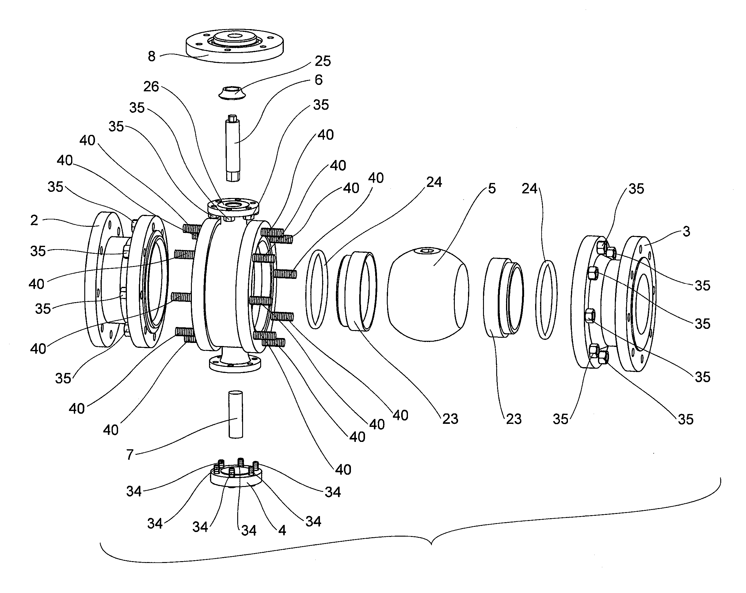
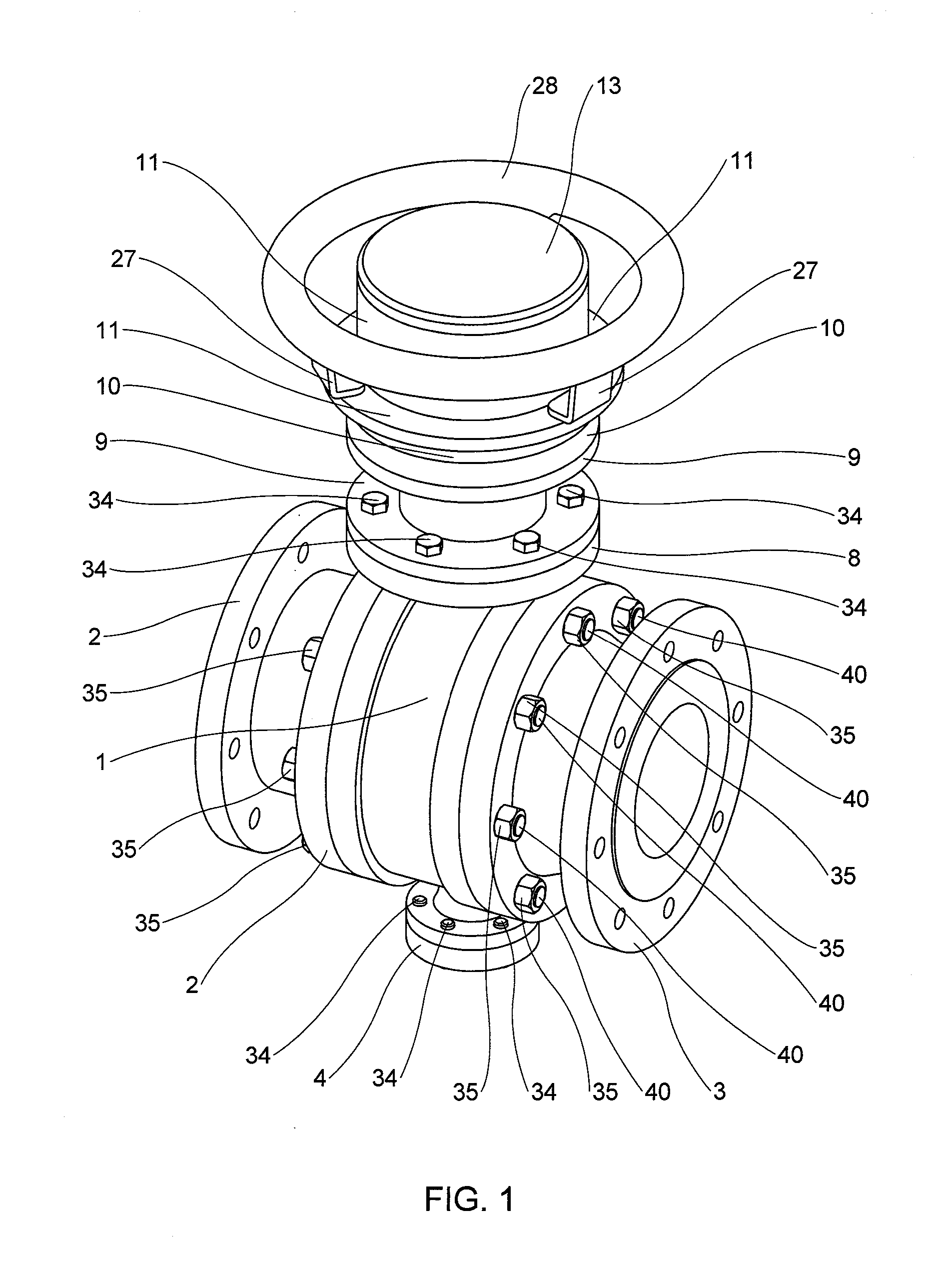
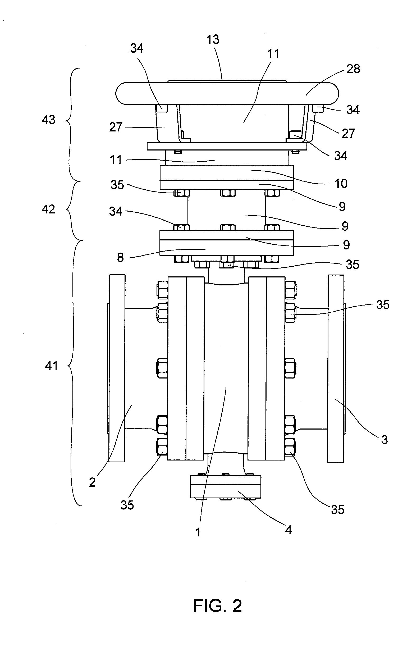
[0143]FIG. 1 is a perspective view of the present invention in a fully assembled state. This figure shows the valve body 1, the left flange 2, the right flange 3, and the trunnion cover 4. The left and right flanges 2, 3 are bolted to the valve body 1 and allow the valve to be connected to piping (not shown). The trunnion cover 4 houses the trunnion 7 (not shown). The present invention comprises an adapter plate 8, which is bolted to the bottom enclosure 9, as well as the valve body 1 (see FIG. 2). Note that the adapter plate 8 may also be integral with (i.e., the same part as) the bottom enclosure 9 rather than a separate part. As shown in subsequent figures, the bottom enclosure 9 contains the planetary gear subassemblies 44.

[0144]The bottom enclosure 9 in turn is bolted to the top enclosure 10, which contains part of the cylindrical magnet wheel actuator assembly 43 (not shown). In an alternate embodiment, the bottom and top enclosures 9, 10 are a single part. The top enclosure 1...


PUM


Abstract

A rotary valve adapter assembly comprising an adapter plate configured to attach to a rotary valve body, a torque multiplier assembly comprising one or more planetary gear subassemblies, each of which comprises a sun gear, a ring gear, and a plurality of planetary gears, a magnetic actuator assembly comprising two sets of magnetically coupled magnets, and a shaft. The magnetic actuator assembly interfaces with the torque multiplier assembly such that when the magnets of the magnetic actuator assembly rotate, they cause the sun gear of a first planetary gear subassembly to rotate and the planetary gears to walk on the ring gear. When the carrier of the first planetary gear subassembly rotates, it causes the sun gear of a second planetary gear subassembly to rotate. When the carrier of the second planetary gear subassembly rotates, the shaft also rotates, thereby causing the valve to open and close.

Description

BACKGROUND OF THE INVENTION[0001]1. Field of the Invention[0002]The present invention relates generally to the field of valves and, more specifically, to a rotary valve adapter assembly with a planetary gear system.[0003]2. Description of the Related Art[0004]A number of patent applications have been filed for valve actuators that mitigate stem leakage through the use of a magnetic interlock. These actuator chambers either enclose the dynamic seal that is present in every valve around the stem of the valves, or they eliminate the need for the seal entirely. This dynamic seal is known as a packing or mechanical seal. The magnetic interlock is employed to transmit force from outside of the actuator chamber to the inside, thus avoiding the penetration of the chamber wall by a mechanical stem actuator. Penetration of the chamber wall would nullify the purpose for the chamber in the first place—to enclose the dynamic seal around the stem and prevent leakage from the seal.[0005]The proble...

Claims


Application Information

Patent Timeline
06 Jun 2013
Publication
US20130140475A1
IPC
F16K31/08
CPC
F16K31/088; F16K31/043; F16K31/055; F16K31/535
Inventors
BURGESS, KEVIN; YAKOS, DAVID