
Foil shaped electro-optical product, semi-finished product and method and apparatus for manufacturing the same

a technology of electro-optical products and foils, which is applied in the manufacture of final products, sustainable manufacturing/processing, thermoelectric devices, etc., can solve the problems of not being able to implement a roll-to-roll process, and achieve the effect of avoiding stretching of the electro-optic structure, regular curvature of the product, and strong curvature of the electro-optic produ

Inactive Publication Date: 2013-06-06
NEDERLANDSE ORG VOOR TOEGEPAST-NATUURWETENSCHAPPELIJK ONDERZOEK (TNO)
View PDF1 Cites 12 Cited by
  • Summary
  • Abstract
  • Description
  • Claims
  • Application Information

AI Technical Summary

Benefits of technology

The patent describes a method for making a device with a polymer layer that is stretched and heat-cured to create a stable substrate for subsequent layers. A planarizing coating is applied to create a smooth surface, followed by an inorganic barrier layer to prevent moisture and oxygen from entering. This composite film can then be used as a substrate for electronic or opto-electronic devices. The method helps create a curved device that can adjust to changes in temperature and sun position to maximize its performance or protect it from overheating.

Problems solved by technology

It is a disadvantage of this method that it cannot be implemented as a roll-to-roll process.

Method used


Image

  • Foil shaped electro-optical product, semi-finished product and method and apparatus for manufacturing the same
  • Foil shaped electro-optical product, semi-finished product and method and apparatus for manufacturing the same
  • Foil shaped electro-optical product, semi-finished product and method and apparatus for manufacturing the same

Examples


Embodiment Construction

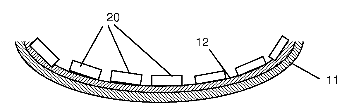
[0102]FIG. 1 shows a curved foil-shaped electro-optical product 1 that has at least a first region with a basis substrate layer 10 of a shrunken organic substance. The basis substrate layer 10 has a convex side 12 and a concave side 14 and the product 1 comprises at the convex side 12 of the basis substrate layer 10 at least a further layer. The electro-optical product 1 further comprises at least a second region with an electro-optical structure 20. The electro-optical structure 20 is for example a stack of layers that converts an electrical current into light. The stack may comprise

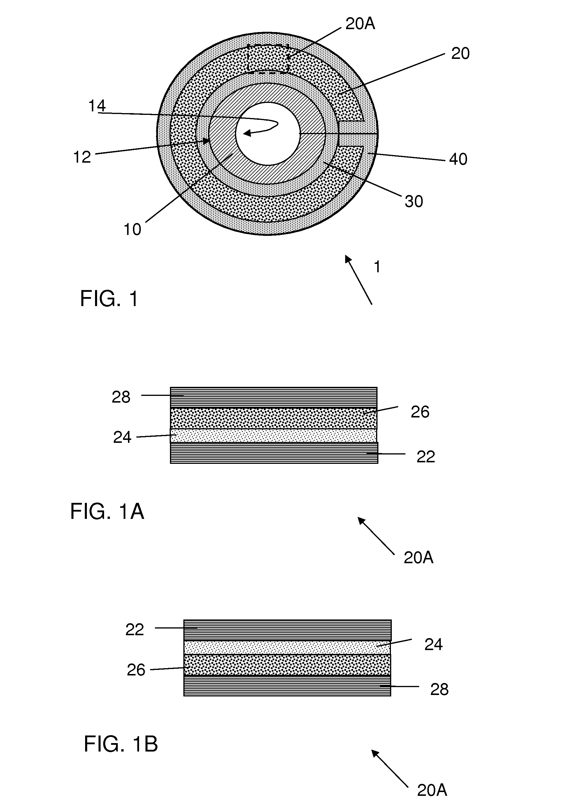
[0103]The electro-optical structure, of which a portion 20A is shown in FIG. 1A typically comprises a stack comprising an anode 22 of a conducting material, a hole transporting layer 24, a light emitting layer 26, and a cathode 28.

[0104]In this case, the anode 22 is preferably formed of a highly reflective metals such as aluminum or silver, so that light radiated inward is reflected outward, but other e...


PUM


Abstract

A curved foil-shaped electro-optical product (1) is provided having at least a first region with a basis substrate layer (10) of a shrunken organic substance, having a convex side and a concave side and comprising at the convex side (12) of the basis substrate layer at least a further layer (20), the electro-optical product further comprising at least a second region with an electro-optical structure (20).

Description

BACKGROUND OF THE INVENTION[0001]1. Field of the Invention[0002]The present invention relates to a foil shaped electro-optical product.[0003]The present invention further relates to a semi-finished foil shaped electro-optical product.[0004]The present invention further relates to a method of manufacturing these products.[0005]The present invention further relates to an apparatus for manufacturing these products.[0006]2. Related Art[0007]An electro-optic device is a device that provides for an optical effect in response to an electric signal, or that generates an electric signal in response to an optical stimulus. Examples of the first are light emitting diodes, such as organic light emitting diodes and electro chromic devices. Examples of the second are photo voltaic cells and optical sensors.[0008]Nowadays such electro-optical devices can be manufactured relatively cheap as a foil in a roll-to-roll process. The devices so obtained have a flat shape. However, for electro-optical dev...

Claims


Application Information

Patent Timeline
Patent Type & Authority Applications(United States)
IPC IPC(8): H01L51/00H10K99/00
CPCH01L51/0097H01L51/52Y02E10/549H01L51/0014H01L2251/5338Y02P70/50H10K77/111H10K2102/311H10K59/80H10K71/20H10K50/80
Inventor DE KOK, MARGARETHA MARIAWILSON, JOANNE SARAHTOONEN, LEONARDUS MARIAMICHELS, JASPER JOOST
Owner NEDERLANDSE ORG VOOR TOEGEPAST-NATUURWETENSCHAPPELIJK ONDERZOEK (TNO)
Learn More