Spindle motor and method of manufacturing the same

Inactive Publication Date: 2013-06-06
SAMSUNG ELECTRO MECHANICS CO LTD
View PDF1 Cites 3 Cited by
  • Summary
  • Abstract
  • Description
  • Claims
  • Application Information

AI Technical Summary

Benefits of technology

[0014]An aspect of the present invention provides a spindle motor capable of suppressing deformation of a portion thereof in which a sleeve and a cover

Problems solved by technology

However, in the case in which the cap member and the cover member are installed on and bonded to the sleeve by the welding, thermal deformation may be generated in the cap member, the cover member, and the sleeve, due to heat caused by the welding.
In addition, the cap member and the cover member may not be completely installed at the time of the generation of the thermal deformation, that is, an excessive amount of welding may be generated or welding may not occur in a portion to be welded, such that lubricating fluid may be leaked.
Further, it may be difficult to confirm these welding defects with the naked eye, such that a process of confirming a welded state of the cap member and the cov

Method used


Image

  • Spindle motor and method of manufacturing the same
  • Spindle motor and method of manufacturing the same
  • Spindle motor and method of manufacturing the same

Examples


Example

[0029]Embodiments of the present invention will now be described in detail with reference to the accompanying drawings. However, it should be noted that the spirit of the present invention is not limited to the embodiments set forth herein and those skilled in the art and understanding the present invention can easily accomplish retrogressive inventions or other embodiments included in the spirit of the present invention by the addition, modification, and removal of components within the same spirit, but those are construed as being included in the spirit of the present invention.

[0030]Further, when it is determined that the detailed description of the known art related to the present invention may obscure the gist of the present invention, the detailed description thereof will be omitted.

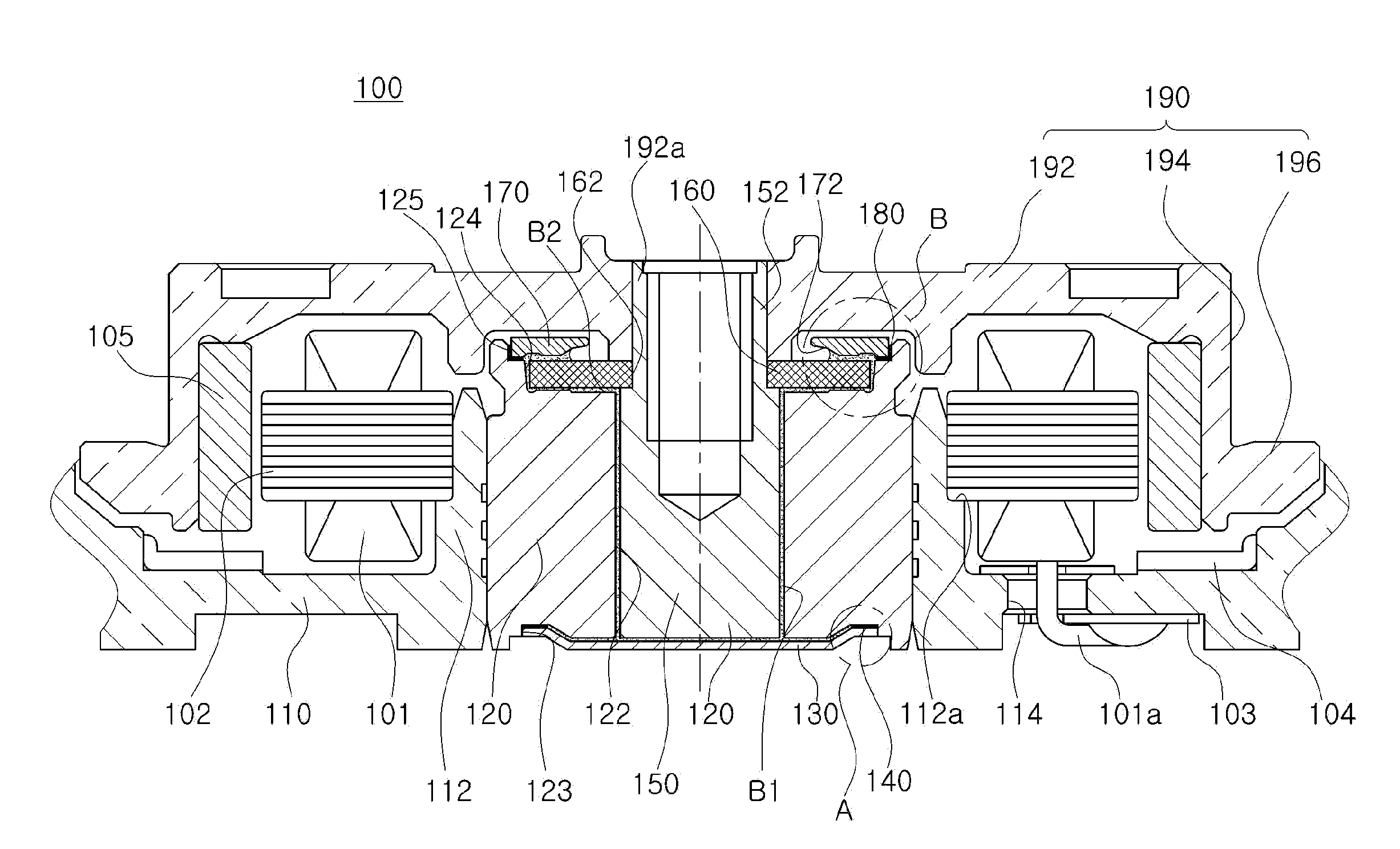
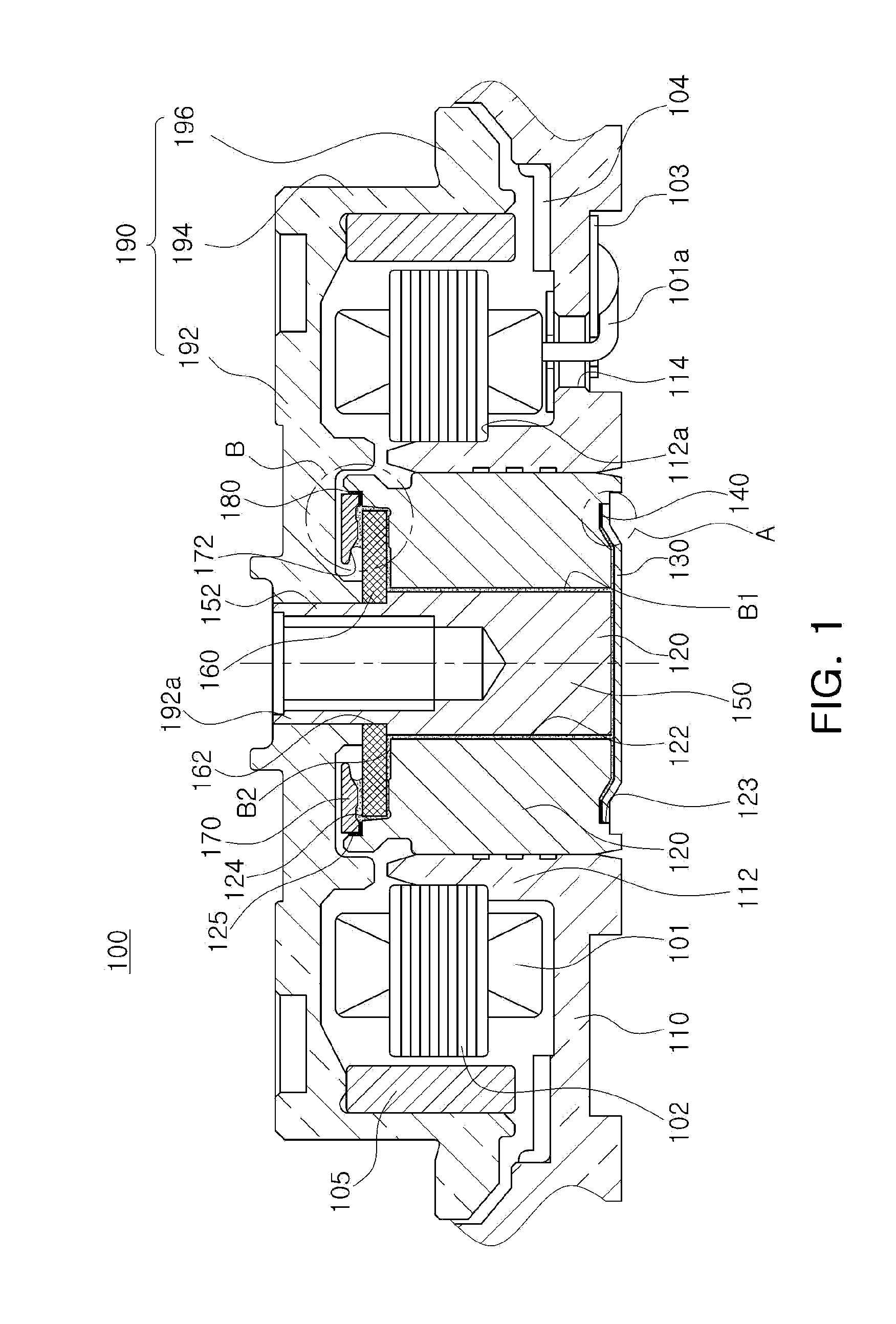
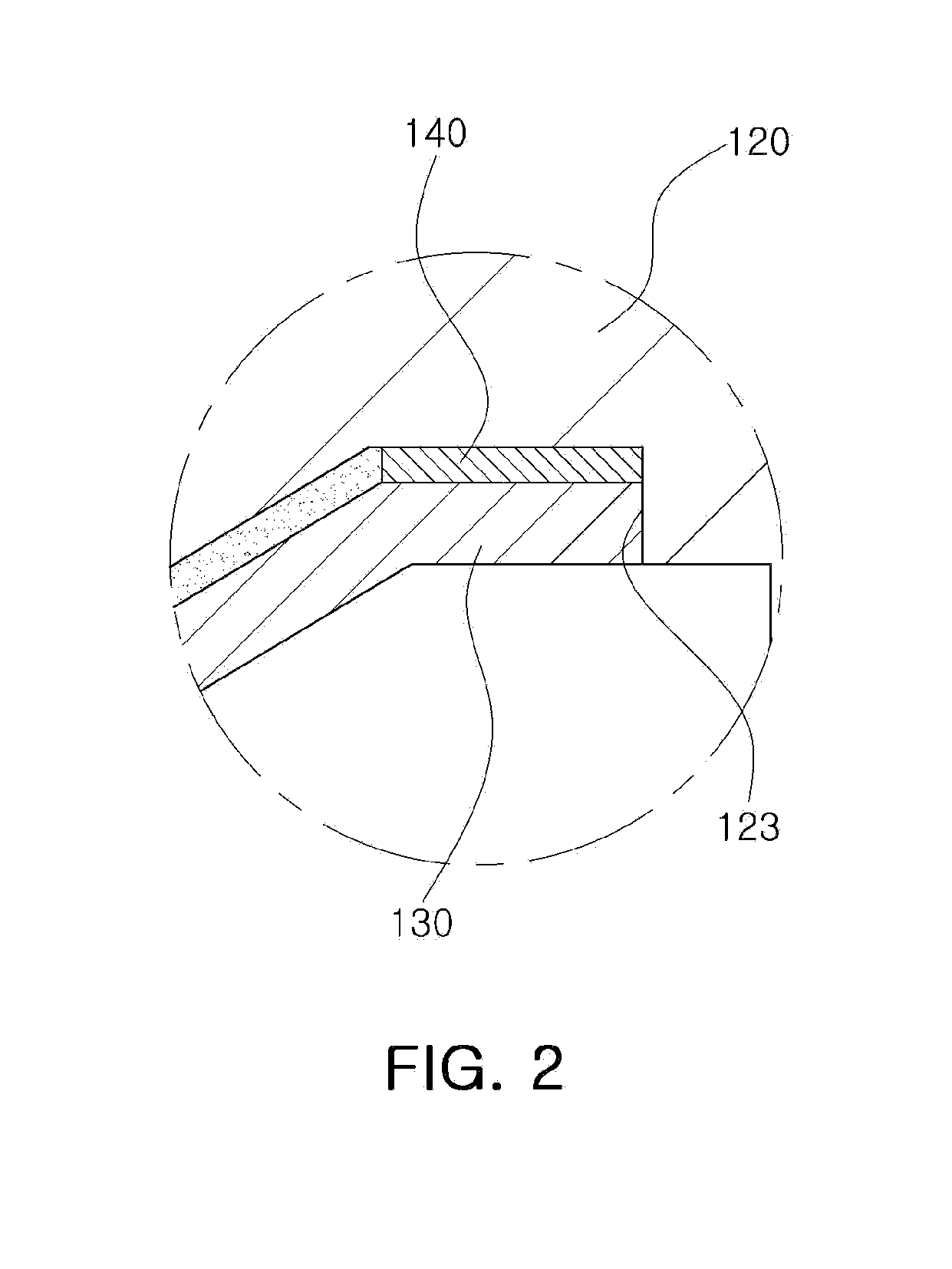
[0031]FIG. 1 is a schematic cross-sectional view showing a spindle motor according to an embodiment of the present invention; FIG. 2 is an enlarged view showing part A of FIG. 1; FIG. 3 is an enlar...


PUM

PropertyMeasurementUnit
Electrical conductoraaaaaaaaaa
Deformation enthalpyaaaaaaaaaa
Anisotropyaaaaaaaaaa

Abstract

There is provided a spindle motor including: a sleeve rotatably supporting a shaft; a cover member installed on a lower end portion of the sleeve; and a bonding member disposed between the sleeve and the cover member such that the cover member is installed on the sleeve and formed of an anisotropic conductive material.

Description

CROSS-REFERENCE TO RELATED APPLICATIONS[0001]This application claims the priority of Korean Patent Application No. 10-2011-0129017 filed on Dec. 5, 2011, in the Korean Intellectual Property Office, the disclosure of which is incorporated herein by reference.BACKGROUND OF THE INVENTION[0002]1. Field of the Invention[0003]The present invention relates to a spindle motor and a method of manufacturing the same.[0004]2. Description of the Related Art[0005]A small-sized spindle motor used for a hard disk drive (HDD) generally includes a fluid dynamic pressure bearing assembly, and a bearing clearance provided in the fluid dynamic pressure bearing assembly is filled with a lubricating fluid.[0006]In addition, at the time of rotation of a shaft, the lubricating fluid filling the bearing clearance is pumped to form fluid dynamic pressure, thereby rotatably supporting the shaft.[0007]Meanwhile, in order to prevent the lubricating fluid filling the fluid dynamic pressure bearing assembly from ...

Claims


Application Information

Patent Timeline
IPC IPC(8): H02K19/02H02K15/00
CPCH02K5/1675H02K15/14G11B19/20
Inventor KIM, YONG SIKPARK, IL OUNGJANG, HO HYUNG
Owner SAMSUNG ELECTRO MECHANICS CO LTD
Why Eureka
Try Eureka