Thermal cycler with vapor chamber for rapid temperature changes

a technology of vapor chamber and cycler, which is applied in the direction of biochemical apparatus and processes, specific use of bioreactors/fermenters, and after-treatment of biomass, etc. it can solve the problems of difficult to achieve uniform temperature changes across all wells or channels, and achieve uniform and rapid temperature changes. uniform

Active Publication Date: 2013-06-06
BIO RAD LAB INC
View PDF5 Cites 24 Cited by
  • Summary
  • Abstract
  • Description
  • Claims
  • Application Information

AI Technical Summary

Benefits of technology

[0008]To address the need for rapid temperature changes in reaction systems that are retained in the wells of a microplate or in any plate or device that contains an array of individual sample receptacles, the various devices and methods disclosed herein involve the placement of a vapor chamber underneath the plate or device, plus heating elements, cooling elements, or both to allow or induce vaporization and condensation of a working fluid in the vapor chamber. The vapor chamber is arranged such that contact with the heated vapor of the working fluid, and condensation of the vapor when cooled, transfer heat into and draw heat from, respectively, the contents of each sample receptacle by conductive heat transfer between the walls of the vapor chamber and the walls of the receptacles. In certain embodiments of the invention, the top of the vapor chamber is in direct contact with the undersides of the receptacles, while in others an intermediary plate is placed between the undersides of the receptacles and the top of the vapor chamber. In embodiments in which the receptacles are wells and the vapor chamber and the wells are in direct contact, the top surface of the vapor chamber has depressions that are shaped and spaced to receive the wells, and to conform in contour with the undersides of the wells to the extent that the depressions are in direct and c...

Problems solved by technology

In general, however, rapid changes in temperature that are u...

Method used


Image

  • Thermal cycler with vapor chamber for rapid temperature changes
  • Thermal cycler with vapor chamber for rapid temperature changes
  • Thermal cycler with vapor chamber for rapid temperature changes

Examples


Embodiment Construction

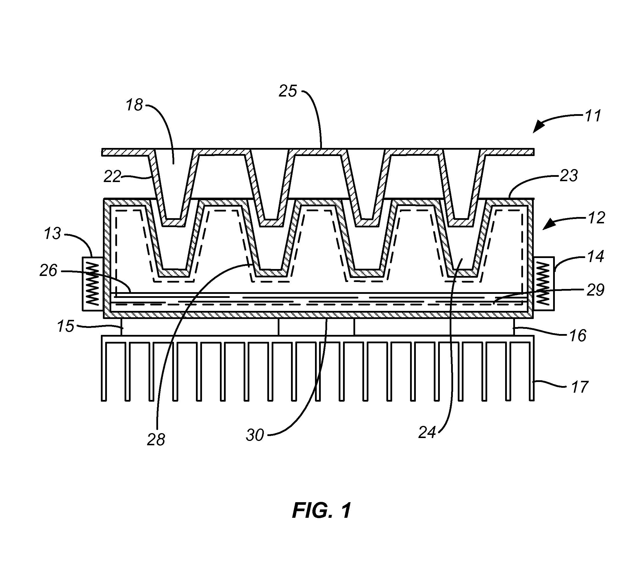
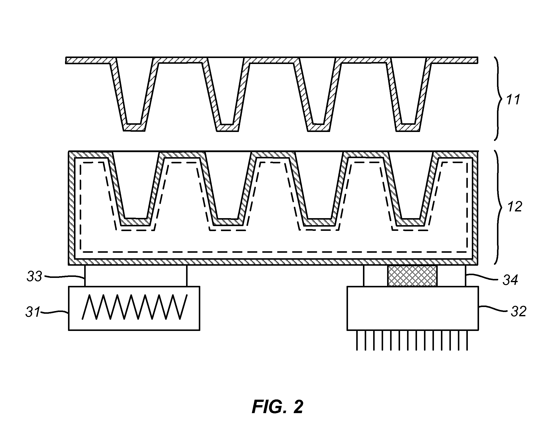
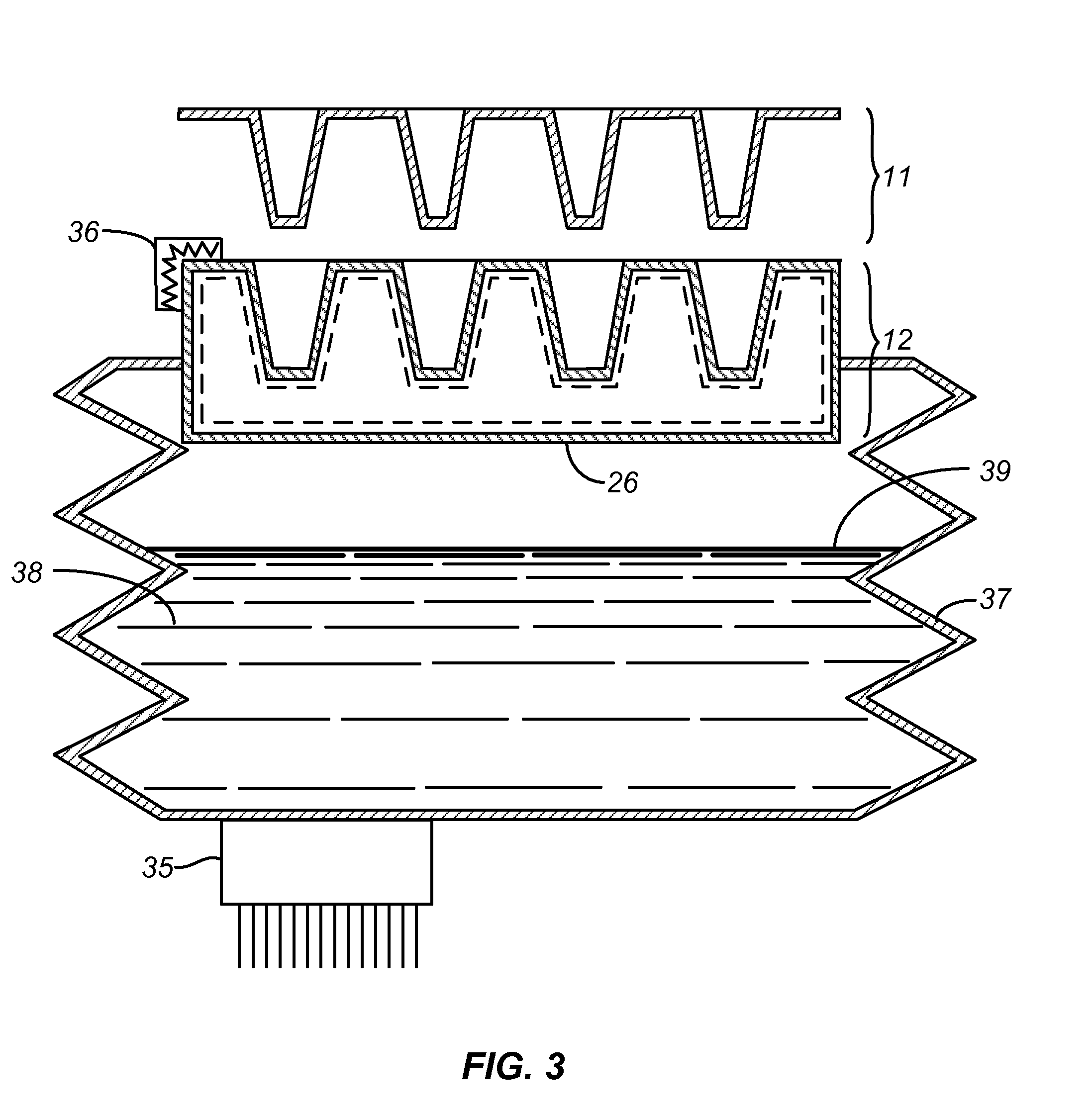
[0019]The vapor chamber that forms a component of each of the systems described herein is a hollow body with a closed internal cavity that contains a working fluid whose vaporization and condensation within the cavity serve as means for promoting or accelerating the transfer of heat out of the cavity into the reaction wells or into the cavity from the reaction wells. Thermal contact between the vapor chamber and the sample receptacles occurs in many cases at the top surface of the vapor chamber, either by direct contact with the undersides of the sample receptacles or through the intermediary plate. To accomplish this, the working fluid is generally partially vaporized so that it exists both in liquid and vapor form within the cavity. Heated vapors tend to rise within the cavity, and upon so doing to contact internal surfaces of cavity wall sections that are in direct contact with the walls of the sample receptacles. Condensation of the vapors at those surfaces releases heat from th...


PUM


Abstract

Rapid and uniform temperature changes in the wells of a microplate or any thin-walled plate that contains an array of reaction wells or sample receptacles are achieved by the use of heating and cooling elements with a vapor chamber interposed between such elements and the microplate. The upper surface of the vapor chamber and the underside of the sample plate in certain embodiments are complementary in shape, i.e., they have identical but oppositely directed contours in the areas around each of the sample receptacles, to provide continuous surface contact along the surface of each receptacle. In other embodiments, an intermediary plate is placed between the vapor chamber and the well plate, with the top surface of the intermediary plate being complementary in shape to the underside of the well plate.

Description

CROSS-REFERENCE TO RELATED APPLICATION[0001]This application claims the benefit of U.S. Provisional Patent Application No. 61 / 483,439, filed May 6, 2011, the contents of which are incorporated herein by reference in their entirety.BACKGROUND OF THE INVENTION[0002]1. Field of the Invention[0003]This invention relates to sequential chemical reactions of which the polymerase chain reaction (PCR) is one example. In particular, this invention addresses methods and apparatus for performing chemical reactions simultaneously in a multitude of reaction mixtures and independently controlling the reaction in each mixture.[0004]2. Description of the Prior Art[0005]PCR is one of many examples of chemical processes that require a high level of temperature control of reaction mixtures with rapid temperature changes between different stages of the procedure. PCR itself is a process for amplifying DNA, i.e., producing multiple copies of a DNA sequence from a single strand bearing the sequence. PCR i...

Claims


Application Information

Patent Timeline
IPC IPC(8): B01L7/00
CPCB01L7/52B01L2300/0829B01L2300/1855B01L2300/1827B01L2300/1822
Inventor GUO, KUNCHU, DANIEL Y.PATT, PAULSADRI, AMIRTONG, ROGER
Owner BIO RAD LAB INC
Why Eureka
Try Eureka