Apparatus and method of measuring porosity and permeability of dioxide carbon underground storage medium

a technology of porosity and permeability, applied in the field of apparatus and method of measuring porosity and permeability of dioxide carbon underground storage medium, can solve the problems of continuous variation of porosity, inability to obtain the characteristic value of the core sample, increased device cost and required time, etc., to prevent denaturalization

Active Publication Date: 2013-06-06
KOREA INST OF GEOSCI & MINERAL RESOURCES
View PDF11 Cites 43 Cited by
  • Summary
  • Abstract
  • Description
  • Claims
  • Application Information

AI Technical Summary

Benefits of technology

[0024]As described above, according to the method and the apparatus for measuring the porosity and permeability of the carbon dioxide underground storage medium of the present invention, the porosity and the permeability of the core sample can be effectively measured in the state that the confining pressure is applied once, so that the core sample can be prevented from denaturalized.

Problems solved by technology

As described above, according to the related art, since the porosity and the permeability of the core sample are separately measured, the device cost and the required time are increased.
In particular, according to the related art, since the procedure of applying and releasing the confining pressure is repeatedly performed with respect to the same core sample, the core sample is denaturalized, so that the characteristic value of the core sample cannot be obtained.
Although the variation characteristic in the porosity and the permeability serves as an important factor in estimating a carbon dioxide underground storage land, the porosity measuring device or the permeability measuring device according to the related art cannot measure the continuous variation of the porosity and the permeability coefficient according to the salt precipitation.

Method used


Image

  • Apparatus and method of measuring porosity and permeability of dioxide carbon underground storage medium
  • Apparatus and method of measuring porosity and permeability of dioxide carbon underground storage medium
  • Apparatus and method of measuring porosity and permeability of dioxide carbon underground storage medium

Examples


Embodiment Construction

[0031]The advantages, the features, and schemes of achieving the advantages and features will be apparently comprehended by those skilled in the art based on the embodiments, which are detailed later in detail, together with accompanying drawings. The present invention is not limited to the following embodiments but includes various applications and modifications. The embodiments will make the disclosure of the present invention complete, and allow those skilled in the art to completely comprehend the scope of the present invention. The same reference numerals will be assigned to the same elements throughout the whole description.

[0032]Hereinafter, an apparatus and a method of measuring the porosity and the permeability of a carbon dioxide underground storage medium according to an exemplary embodiment of the present invention will be described in detail with reference to accompanying drawings.

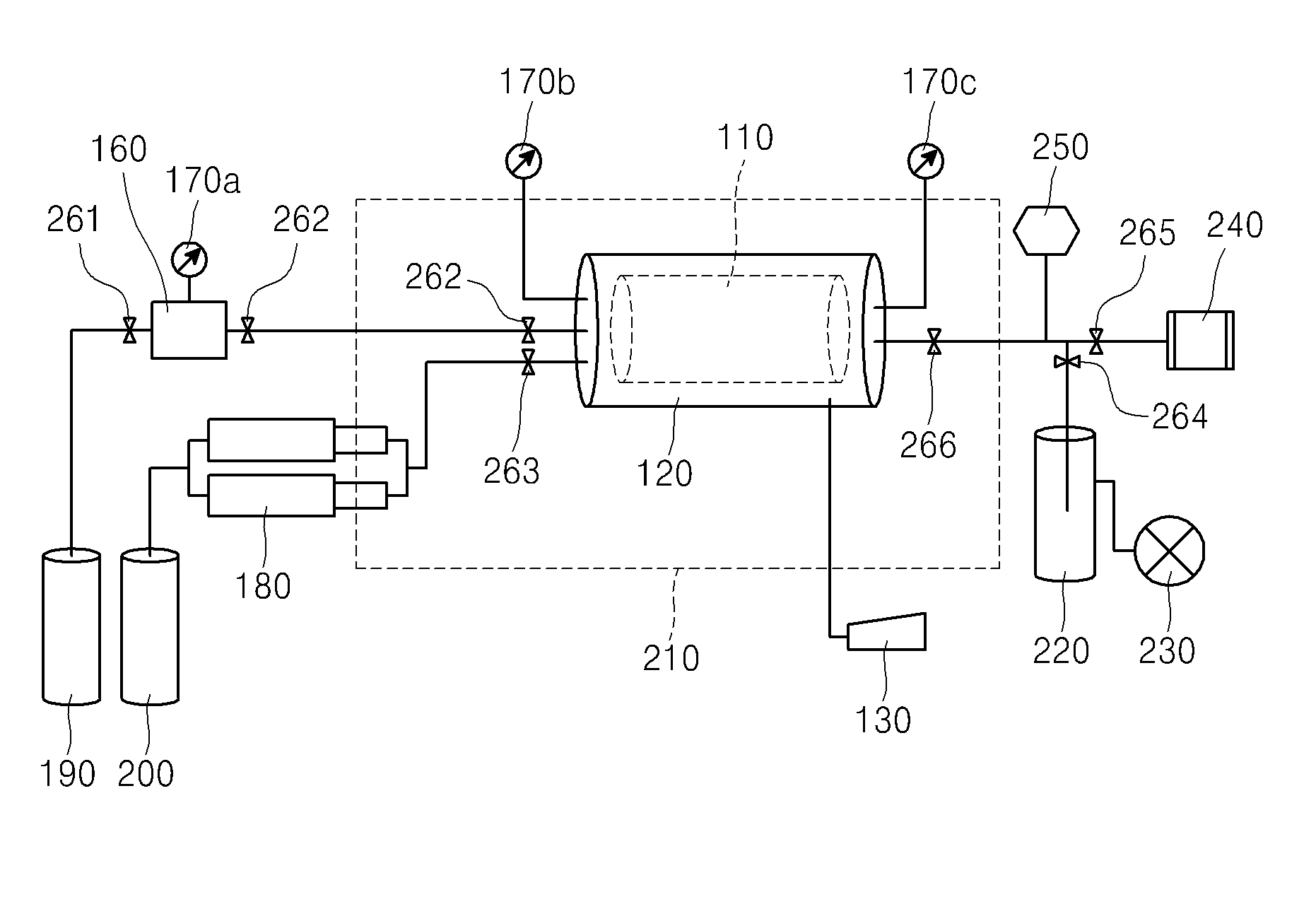
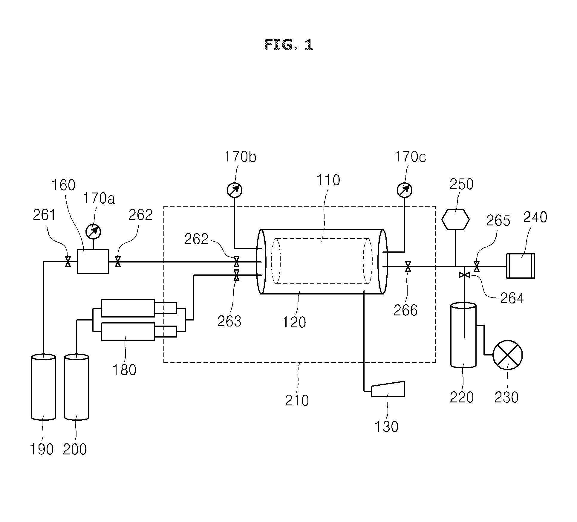
[0033]FIG. 1 is a schematic view showing an apparatus for measuring the porosity and the p...


PUM

PropertyMeasurementUnit
porosityaaaaaaaaaa
permeabilityaaaaaaaaaa
pressureaaaaaaaaaa

Abstract

Disclosed are an apparatus and a method of measuring porosity and permeability of a carbon dioxide underground storage medium. Both of the porosity and the permeability are measured in the state that the confining pressure is applied once. The variation characteristic in the porosity and the permeability of the core sample according to the salt precipitation occurring when supercritical carbon dioxide is injected is continuously measured. The apparatus includes a holder receiving a core sample, a pressure pump applying a confining pressure to the core sample, a gas chamber storing gas and supplying supply the stored gas to the core sample, first to third pressure gauges measuring an internal pressure of the gas chamber and front and rear portions of the holder, and a gas flow meter measuring a flow rate of gas.

Description

CROSS-REFERENCE TO RELATED APPLICATION[0001]This application claims the benefit under 35 U.S.C. §119 of Korean Patent Application No. 10-2011-0129247 filed on Dec. 5, 2011 in the Korean Intellectual Property Office, the entirety of which disclosure is incorporated herein by reference.BACKGROUND OF THE INVENTION[0002]1. Field of the Invention[0003]The present invention relates to a technology of analyzing the storage capacity of a land for the underground storage of carbon dioxide and the injection characteristic of the land for the underground storage of the carbon dioxide. In more detail, the present invention relates to a method and an apparatus for measuring porosity and permeability of a carbon dioxide underground storage medium, capable of measuring the porosity and the permeability of the carbon dioxide underground storage medium by using one device, and continuously measuring the variation characteristic in the porosity and the permeability of the carbon dioxide underground s...

Claims


Application Information

Patent Timeline
Patent Type & Authority Applications(United States)
IPC IPC(8): G01N15/08G06F19/00
CPCG01N15/0806G01N15/088G01N15/0826G01N15/08
Inventor KIM, KUE-YOUNGOH, JUN-HOKIM, TAE-HEE
Owner KOREA INST OF GEOSCI & MINERAL RESOURCES
Why Eureka
Try Eureka