
Hydrostatic radial piston machine

a radial piston machine and hydraulic technology, applied in reciprocating piston engines, engines with rotating cylinders, positive displacement liquid engines, etc., can solve the problems of greater leakage rates, difficult connection between the outer enveloping surface of the control pinion and the inner enveloping surface of the rotating radial cylinder block, and the mechanical bending load on the control pinion is rather high, etc., to achieve convenient connection, facilitate connection, and support simple

Active Publication Date: 2013-06-13
BERBUER JUERGEN
View PDF4 Cites 1 Cited by
  • Summary
  • Abstract
  • Description
  • Claims
  • Application Information

AI Technical Summary

Benefits of technology

The invention is a new design for a radial piston engine, which has high pressure load bearing capability and is robust against pressure surges and vibrations. It uses a special control plate design that is engaged with the cylinder block and the housing to react the radial forces during operation. The control plate elements are disc-shaped with faces perpendicular to the rotation axis, which prevents any reaction to the radial forces. The design also allows for a closed force flow and minimizes sound emissions. The machine is suitable for applications in water hydraulics, which have inferior lubrication properties. The support portion of the radial cylinder block has a conical shape, which matches the bearing portion of the control plate element. The conical angle of the control plate element is between 90 degrees and 150 degrees. The radial cylinder block and control plate element engage in axial direction as male and female parts.

Problems solved by technology

Disadvantages of this very widely used configuration are that only rather narrow flow channels (inlet and outlet channels) can be implemented in the control pinion and that due to the flow channels axially run out of the control pinion, the mechanical bending load on the control pinion is rather high.
However, the fit between the outer enveloping surface of the control pinion and the inner enveloping surface of the rotating radial cylinder block is rather problematic.
Therein due to the configuration no zero gap is feasible, wherein the leakage increases with the third power of the clearance, which yields greater leakage rates in particular for increasing wear.
Furthermore the known principle of control pinion radial cylinder block fit is sensitive to hydraulic fluids contaminated with dirt particular and sensitive to rapid temperature changes.
Problems of this configuration are large axial forces and the need to support these large axial forces in a permanent manner with little wear.
Furthermore the radial reactive forces from the hydraulic pressure impact the shaft and have to be received by the shaft bearings.
This in turn leads to an increased complexity for the shaft and its support and to potential wear.
In the single stroke machines with eccentric lifting ring the known principle, however, leads to significant friction and significant requirements with respect to the shaft bearing.
For these reasons the solutions according to the three older printed documents have not been used in practical applications.

Method used


Image

  • Hydrostatic radial piston machine
  • Hydrostatic radial piston machine
  • Hydrostatic radial piston machine

Examples


Embodiment Construction

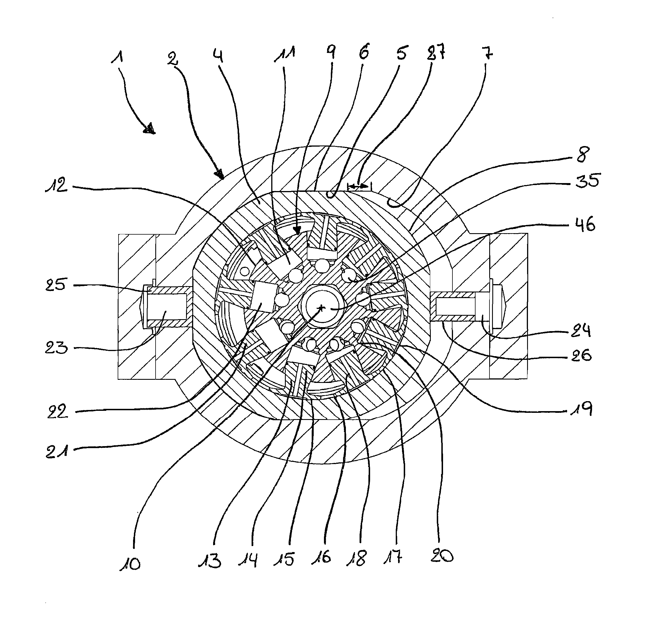
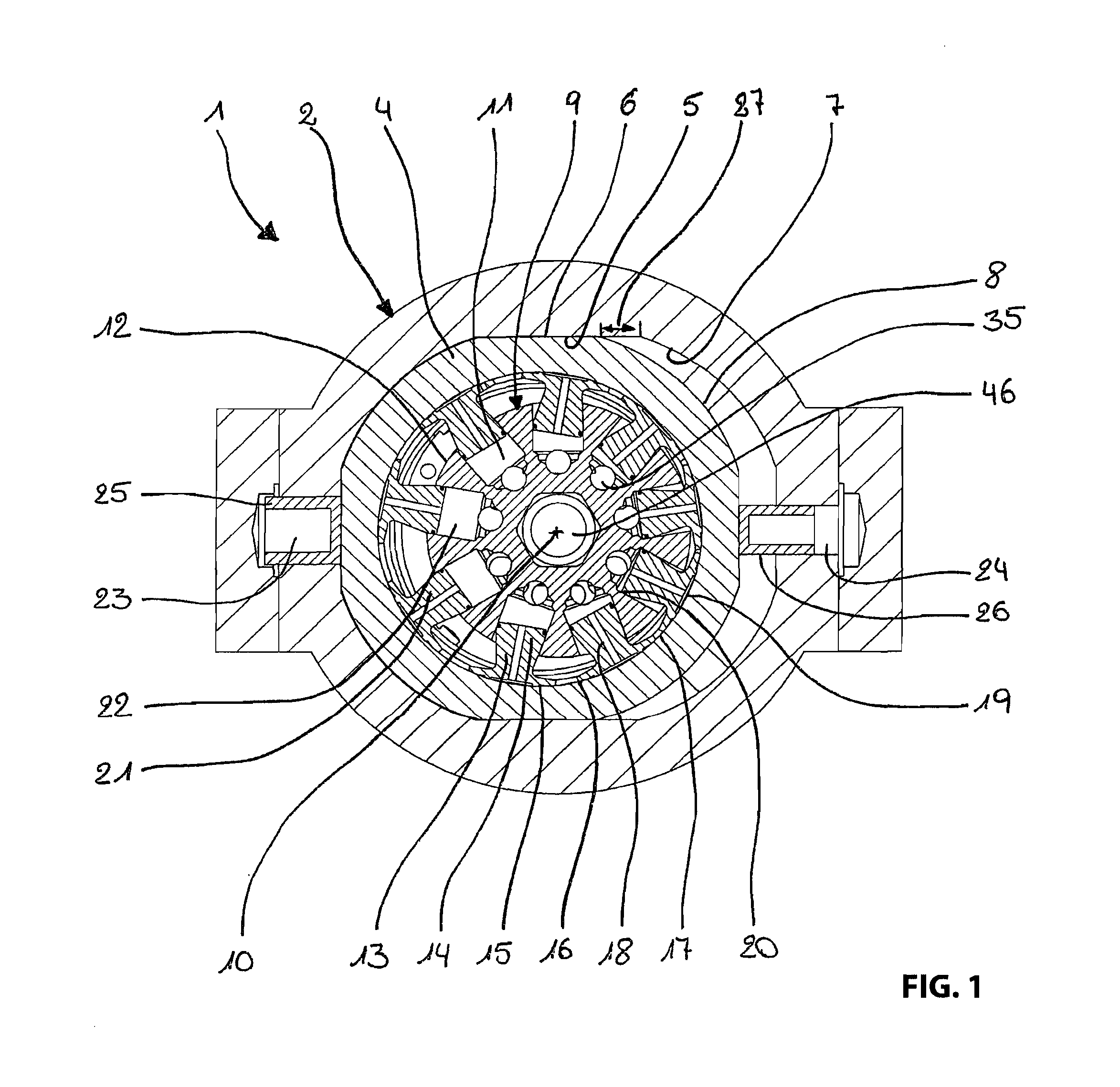
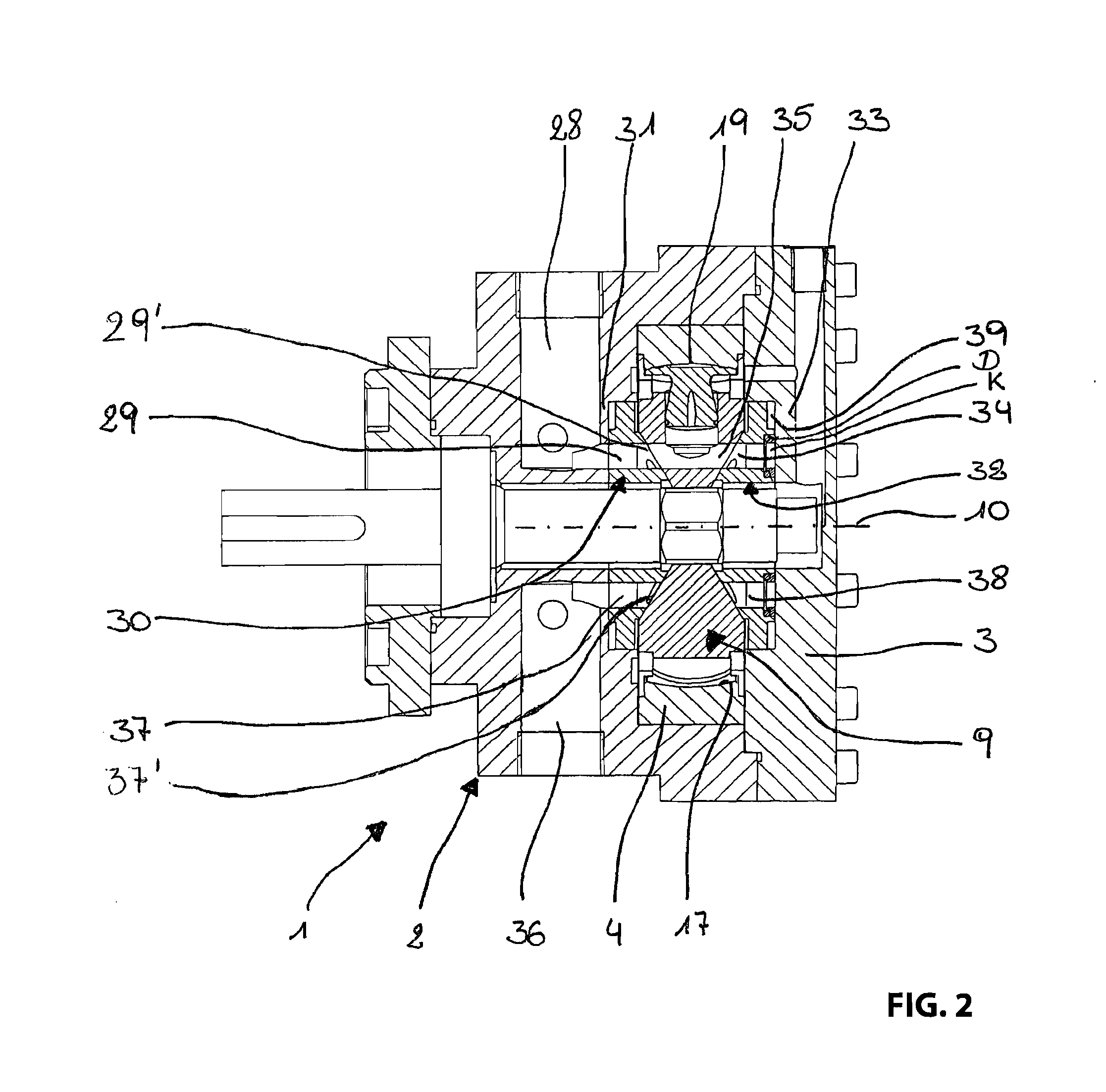
[0027]A radial piston machine 1 illustrated in FIGS. 1, 2 and 2a includes a housing 2 which is closed fluid tight viewed in axial direction on one side with a housing cover 3. A cam ring 4 is moveably arranged in the housing 2, thus moveable along two respective surfaces 5 which are configured on one side on an inner enveloping surface 7 of the housing 2 and on the other side at an outer enveloping surface 8 of the cam ring.

[0028]The radial piston machine 1 furthermore includes a rotor configured as a radial cylinder block 9 which is rotatable about a rotation axis 10. In the present case the cylinder block 9 includes nine bores 11 evenly distributed over a circumference of the radial cylinder block 9 and starting from an outer enveloping surface 12 of the radial cylinder block 9 and extending in radial direction into an interior of the radial cylinder block 9, this means towards the rotation axis 10.

[0029]A piston 13 is moveably arranged in each bore 11, wherein each piston 13 incl...


PUM


Abstract

A hydrostatic radial piston machine includes a radial cylinder block with cylinder bores which extend from an outer circumferential surface of the radial cylinder block into an interior of the radial cylinder block a number of pistons which corresponds to the number of cylinder bores; a cam ring and ends of the pistons which face away from the radial cylinder piston block are supported movably on an inner circumferential surface of the radial cylinder block during a rotation of the radial cylinder block; two control plate elements which extend respectively with a face oriented towards the radial cylinder block towards a central plane of the radial cylinder block, which central plane is perpendicular to the rotation axis. Each control plate element includes a bearing portion in which radially acting forces are transferable to a respective mating surface in the housing or housing cover mounted in the housing.

Description

RELATED APPLICATIONS[0001]This application is a continuation of PCT / EP2010 / 069078 filed on Dec. 7, 2010 claiming priority from German patent application DE 10 2009 054 548.4 filed on Dec. 11, 2009.FIELD OF THE INVENTION[0002]The invention relates to a hydrostatic radial piston machine including: a housing; a radial cylinder block rotatably supported in the housing about a rotation axis and including a plurality of bores extending from an outer enveloping surface of the radial cylinder block into an interior of the radial cylinder block and arranged distributed over a circumference of the radial cylinder block; a plurality of pistons which corresponds to the plurality of bores which pistons are movably supported in the bores and respectively define an operating cavity for a hydraulic fluid together with an associated bore; a cam ring which is arranged eccentric relative to the radial cylinder block and which circumferentially envelops the radial cylinder block and wherein ends of the...

Claims


Application Information

Patent Timeline
Patent Type & Authority Applications(United States)
IPC IPC(8): F04B1/06F04B1/107F01B13/06
CPCF03C1/0444F04B1/0465F04B1/1072F01B13/062F04B1/063F04B1/1071
Inventor BERBUER, JUERGEN
Owner BERBUER JUERGEN
Learn More