Internal combustion engine and method of producing same

a combustion engine and internal combustion technology, applied in the direction of machines/engines, mechanical equipment, coatings, etc., can solve the problems of reducing the efficiency of intake and knocking, difficult to say that the structure of the coating film has an excellent pressure relaxation or stress relaxation behavior, and it is difficult to set up a satisfactory stress relaxation between these cells, etc., to achieve excellent heat insulation behavior, excellent ability to relax expansion pressure, and high durability

Active Publication Date: 2013-06-13
TOYOTA JIDOSHA KK
View PDF0 Cites 51 Cited by
  • Summary
  • Abstract
  • Description
  • Claims
  • Application Information

AI Technical Summary

Benefits of technology

[0041]As can be understood from the preceding description, the internal combustion engine and method for its production of the invention through the formation, on all or a portion of a wall of a combustion chamber of the internal combustion engine, of an anodic oxidation coating film having a structure that has a void (the first void) in the interior of the hollow cells and that also has a void (the second void) at, for example, the triple points among adjacent hollow cells, while chemical b

Problems solved by technology

However, these ceramics generally have a low thermal conductivity and have a high heat capacity, causing the appearance of a reduced intake efficiency and knocking (abnormal combustion caused by heat being retained within the combustion chamber), and as a consequence at the present time their use as a coating film material on the interior walls of the combustion chamber is not spreading.
Moreover, in addition to this low thermal conductivity and low heat capacity, the coating film is desirably formed from a material that can Withstand the expansion pressure and injection pressure during combustion in the combustion chamber and the repetitive stresses from thermal expansion and thermal shrinkage and is also desirably formed from a material that has a high adherence to the base material of, e.g., the cylinder block an

Method used


Image

  • Internal combustion engine and method of producing same
  • Internal combustion engine and method of producing same
  • Internal combustion engine and method of producing same

Examples


Embodiment Construction

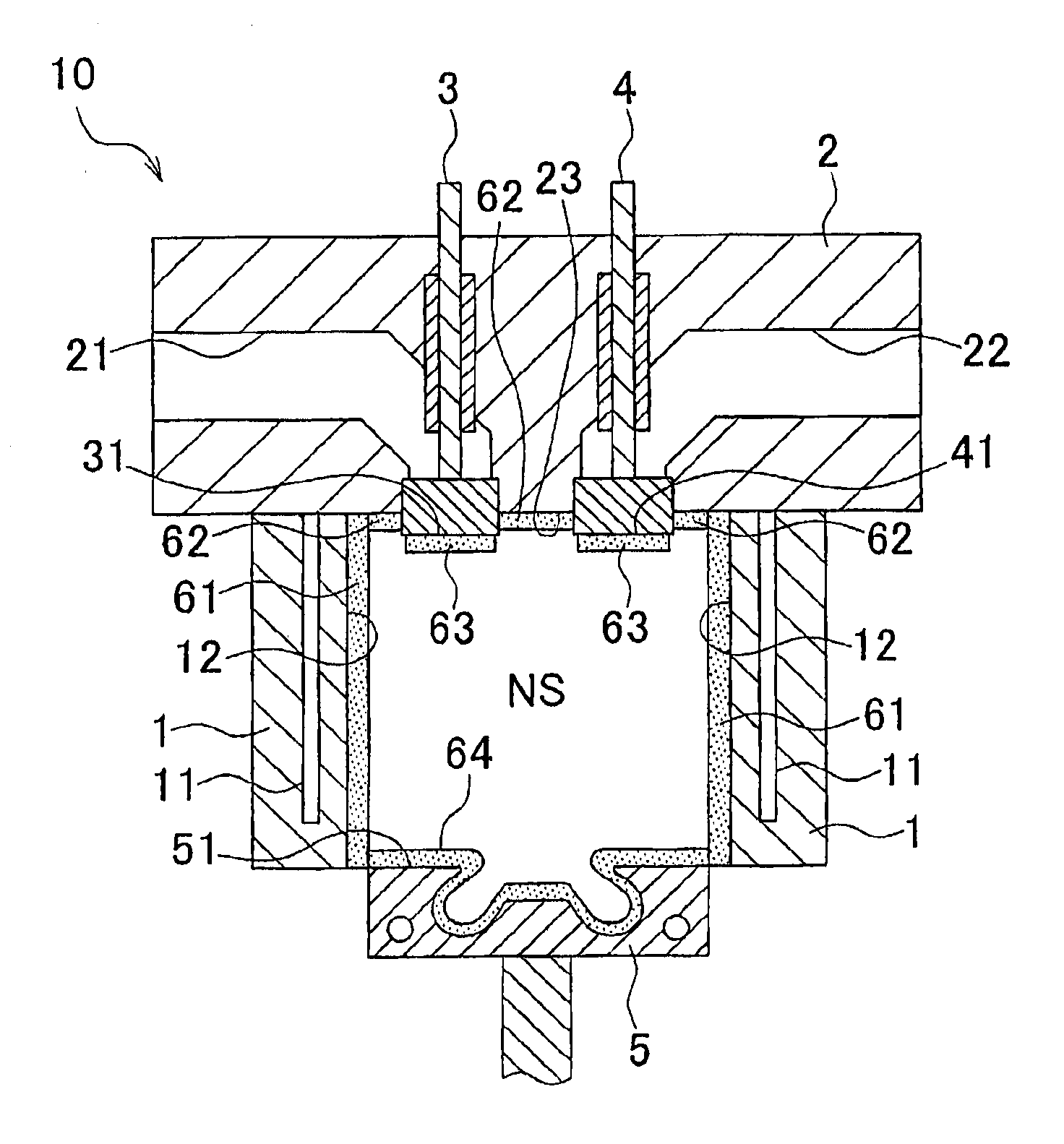
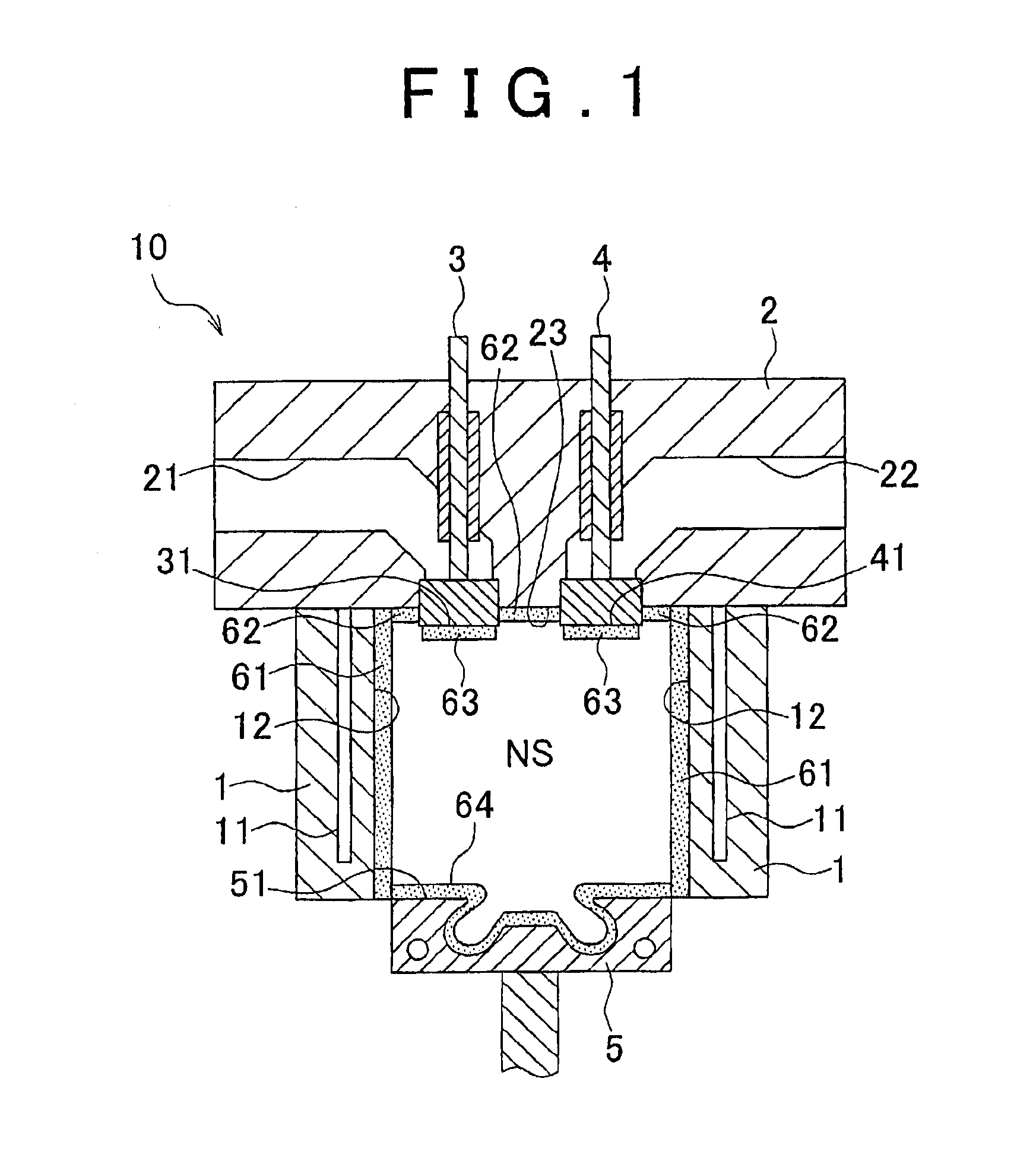
[0082]Embodiments of the internal combustion engine and the method of its production of the invention are described below with reference to the drawings. While the illustrated examples show embodiments in which the anodic oxidation coating film is formed over the entire wall facing the combustion chamber of the internal combustion engine, embodiments may also occur in which the anodic oxidation coating film is formed on only a portion of the wall facing the combustion chamber, e.g., only on the top Surface of the piston or only on the head surface of the valve.

[0083]FIG. 1 is a longitudinal cross-sectional view of an embodiment of the internal combustion engine of the invention; FIGS. 2A and 2B are drawings that show the thin film and the microstructure of an anodic oxidation coating film facing the combustion chamber of an internal combustion engine; and FIG. 3A is a flowchart of an embodiment of the method of producing an internal combustion, engine of the invention.

[0084]The il...


PUM

PropertyMeasurementUnit
Temperatureaaaaaaaaaa
Thicknessaaaaaaaaaa
Electric potential / voltageaaaaaaaaaa

Abstract

An internal combustion engine in which an anodic oxidation coating film is formed on all or a portion of a wall that faces a combustion chamber, wherein the anodic oxidation coating film has a structure that is provided with a bonding region in which each of hollow cells forming the coating film is bonded to the adjacent hollow cells, and a nonbonding region in which three or more adjacent hollow cells are not bonded to each other, and wherein a porosity of the anodic oxidation coating film is determined by a first void present in the hollow cell and a second void that forms the nonbonding region.

Description

BACKGROUND OF THE INVENTION[0001]1. Field of the Invention[0002]The invention relates to an internal combustion engine and a method of producing this internal combustion engine. More particularly, the invention relates to an internal combustion engine in which an anodic oxidation coating film is formed on all or a portion of the wall facing a combustion chamber of the internal combustion engine and relates to a method of producing an internal combustion engine having a feature in forming this anodic oxidation coating film.[0003]2. Description of the Related Art[0004]An internal combustion, engine, e.g., a gasoline engine or diesel engine, is composed primarily of an engine block and a cylinder head, and its combustion chamber is defined by the bore surface of the cylinder block, the top surface of the piston installed in this bore, the bottom surface of the cylinder head, and the head surfaces of the intake and exhaust valves that are disposed in the cylinder head. Accompanying the ...

Claims


Application Information

Patent Timeline
IPC IPC(8): F02B77/02
CPCC25D11/04C25D11/24C25D11/246F01L3/04F02B77/02Y10T29/49272F02F1/18F02F3/12F02F3/14F05C2251/048Y10T29/49263F02B77/11
Inventor HIJII, TAKUMINISHIKAWA, NAOKIKAWAGUCHI, AKIONAKATA, KOICHIWAKISAKA, YOSHIFUMIKOSAKA, HIDEMASASHIMIZU, FUMIO
Owner TOYOTA JIDOSHA KK
Why Eureka
Try Eureka