Thermal management of photonics assemblies

a technology of photonics and thermal management, applied in semiconductor lasers, semiconductor/solid-state device details, lighting and heating apparatus, etc., to achieve the effect of efficient isolation of photonics assemblies and dissipation of heat load generated

Active Publication Date: 2013-06-13
WSOU INVESTMENTS LLC
View PDF35 Cites 31 Cited by
  • Summary
  • Abstract
  • Description
  • Claims
  • Application Information

AI Technical Summary

Benefits of technology

[0004]Therefore a method suitable for efficiently isolating photonics assemblies while mai

Problems solved by technology

Fluidic cooling has not previously been used for photonics assemblies, because of problems with temperature control and

Method used


Image

  • Thermal management of photonics assemblies
  • Thermal management of photonics assemblies
  • Thermal management of photonics assemblies

Examples


first embodiment

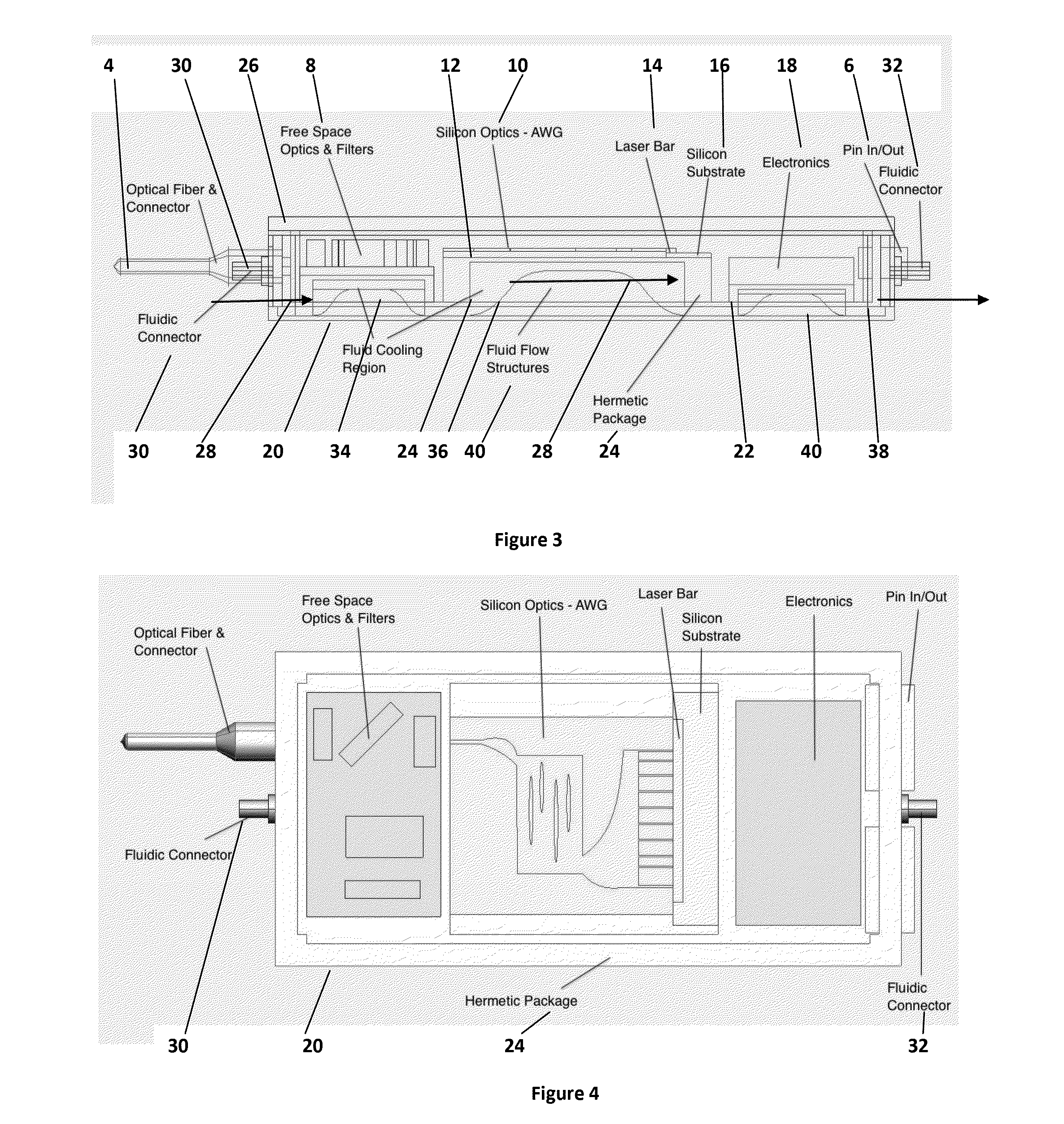
[0035]Referring now to the invention shown in FIGS. 3, 4 and 5, similar parts to those of FIGS. 1 and 2 are denoted by the same reference numeral. An outer open container 20 of thermally isolating plastic material receives a registering base portion 22 of a hermetic package 24 (shown in exploded form in FIG. 5), of a thermally conductive metallic material. A top surface 26 of thermally insulating material completes both the hermetic package, and the outer container. The layout of the electronic and photonic components is similar to that of FIGS. 1 and 2, and it may be seen from FIG. 5 that units 8-18 together comprise a single composite assembly 17, with the conductive silicon substrate of each unit 8-18 forming a composite thermally conductive substrate assembly 19. The substrate assembly may be separate substrate units or joined together units, or be formed as an integral unit.

[0036]Fluidic cooling of the components is provided as follows. Between container structure 20 and base 2...

second embodiment

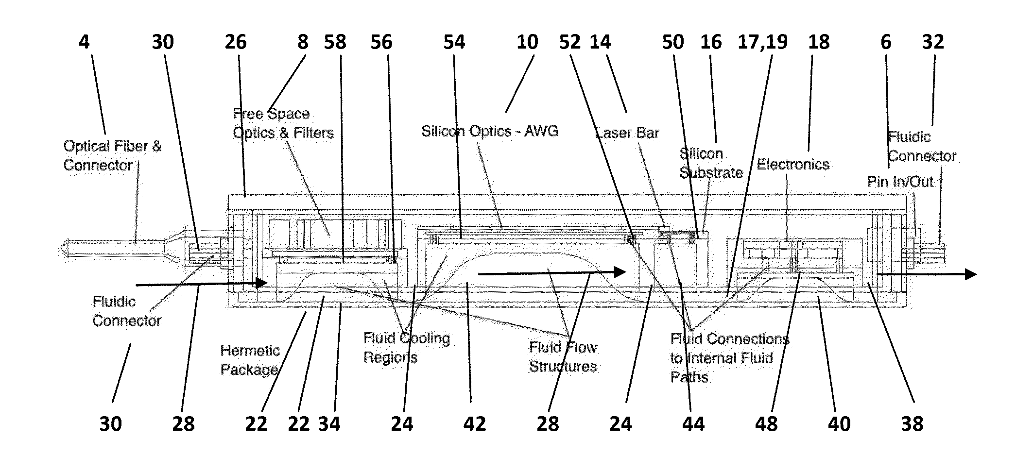
[0037]Referring now to the second embodiment shown in FIGS. 6 to 11, similar parts to those of FIGS. 3 to 5 are denoted by the same reference numerals. Referring firstly to FIG. 8, the outer container 20 has a top cover 27 of insulating material, with side flanges 29 which overlap base 20, to completely envelope sealed container 24. In this case top 26 of container 24 may be thermally conductive. For clarity, top 27 is not shown in FIGS. 6 and 7.

[0038]In FIG. 6, recess 36 of FIG. 3 has been modified as a first recess 42 beneath waveguides 12 separated by an intervening wall from a second recess 44 disposed beneath laser bar 14. Although the base 22 retains the hermetic seal of the first embodiment, the upper floor of each recess is formed with internal inlet and outlet fluid flow paths, directed to the electronics and photonics components. Thus in recess 38, see FIGS. 6 and 9, fluid flow paths 48 are provided for conducting fluid into contact with electronics components. In recess 4...


PUM


Abstract

A photonics assembly (8-16) is housed within an hermetically sealed container (24) mounted within an outer container (20), and is cooled by a fluidic arrangement comprising a liquid flow path (28) defined between the outer container and the sealed container, the outer container having a liquid inlet and a liquid outlet (30, 32), whereby cooling liquid can flow around the hermetically sealed container to remove heat. The photonics assembly including photonics devices, has a composite thermally conductive substrate (17, 19) contacting a thermally conductive wall (22) of the sealed container, whereby the cooling liquid cools said photonics devices. Liquid flow passageways (48-66) are provided in wall (22) and substrate (17, 19) for improving fluidic cooling.

Description

TECHNICAL FIELD[0001]The present invention relates to thermal management of optical and / or electrical component assemblies, particularly though not exclusively photonics component assemblies.BACKGROUND ART[0002]The current common method of controlling the temperature of photonics assemblies, for example one or more photonics devices mounted in a circuit pack, is the use of thermoelectric modules (TE). These are very inefficient modes of thermal control. Photonic sub-assemblies typically operate at a fixed temperature but are placed within modules and on circuit packs where they can have a requirement as the lowest temperature component, which results in heat load being drawn into the package. Currently one solution uses a heat spreading material in conjunction with a thermoelectric module. The module is powered to maintain a set point temperature and localized heating methods are employed to control specific component or location temperatures. For optic components this involves the ...

Claims


Application Information

Patent Timeline
IPC IPC(8): H05K7/20
CPCH05K7/20281H01L23/473H01S5/02423H01S3/0407H01L2924/0002H01L2924/00
Inventor DALY, JOHN
Owner WSOU INVESTMENTS LLC
Why Eureka
Try Eureka