

Induction load driving system
- Summary
- Abstract
- Description
- Claims
- Application Information
AI Technical Summary
Benefits of technology
Problems solved by technology
Method used
Image

Examples
embodiment 1
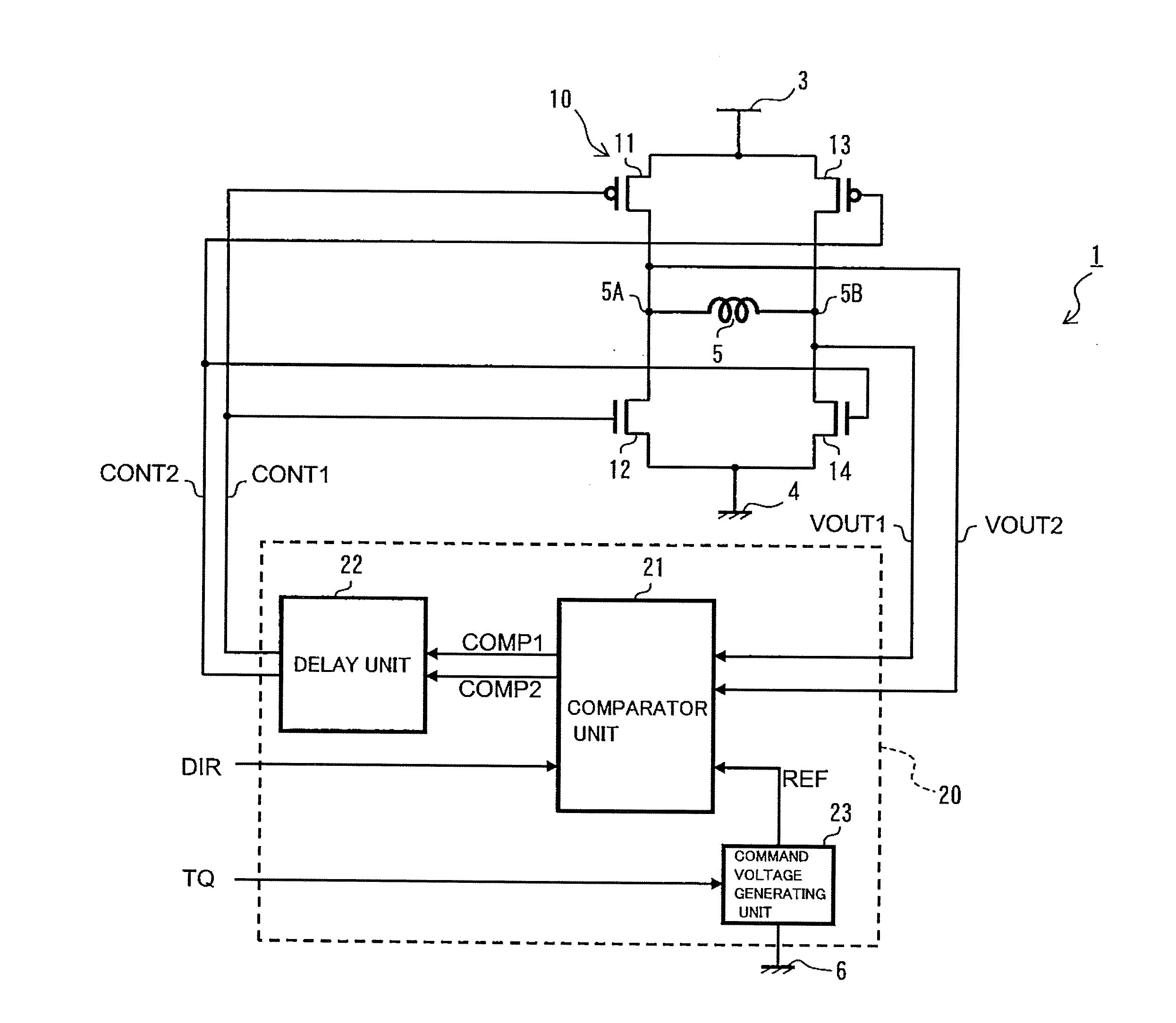
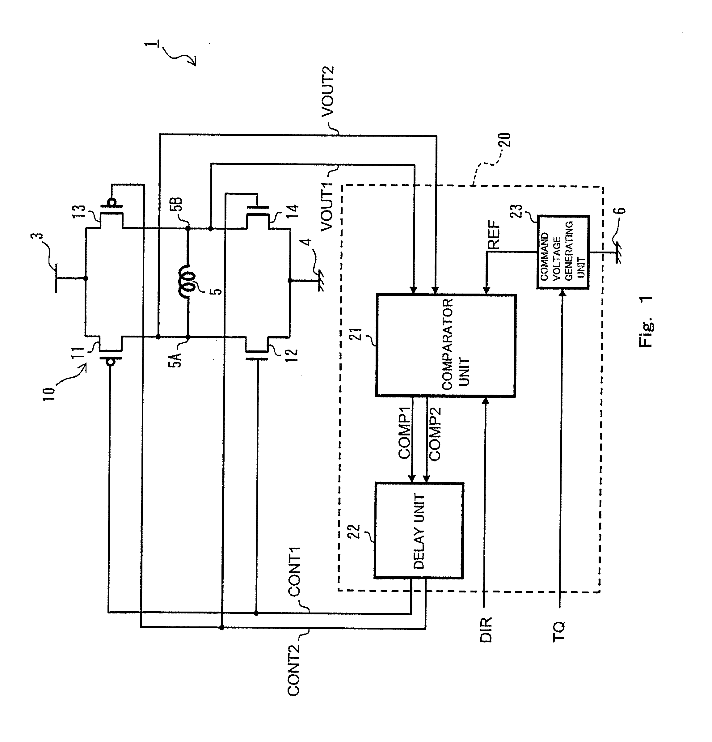
[0036]First of all, an induction load driving system of Embodiment 1 of the present invention will be described. FIG. 1 is a circuit diagram showing a schematic configuration of the induction load driving system according to Embodiment 1 of the present invention.
[0037]Referring to FIG. 1, an induction load driving system 1 of the present embodiment includes a H-bridge circuit 10 for bidirectionally flowing a current through an induction load 5 such as a coil, and a control signal generating circuit 20 for generating a control signal used to control switching of the H-bridge circuit 10. The H-bridge circuit 10 is provided between a first power supply unit 3 for generating a predetermined voltage and a second power supply unit 4 for generating a voltage different from the voltage of the first power supply unit 3, and is configured to flow a current from the first power supply unit 3 to the second power supply unit 4 via the induction load 5. In the present embodiment, the first power ...
modified example of embodiment 1
[0097]Next, a modified example of the induction load driving system according to Embodiment 1 of the present invention will be described. The induction load driving system of the present modified example is different from the induction load driving system of Embodiment 1 in the configuration (FIG. 2) of the comparison unit 21 of Embodiment 1. FIG. 5 is a circuit diagram showing a schematic configuration of the comparison unit in the induction load driving system according to the modified example of Embodiment 1 of the present invention. In the present modified example, the same components as those of Embodiment 1 are designated by the same reference symbols and will not be described in repetition. In the present modified example, the overall configuration (FIG. 1) of the induction load driving system and the output waveforms (FIGS. 3A to 3C and 4A to 4C) are similar to those of Embodiment 1. A comparison unit 21B of the present modified example is configured to include only one comp...
embodiment 2
[0103]Next, an induction load driving system according to Embodiment 2 of the present invention will be described. FIG. 6 is a circuit diagram showing a schematic configuration of the induction load driving system according to Embodiment 2 of the present invention. In the present embodiment, the same components as those of Embodiment 1 are designated by the same reference symbols and will not be described in repetition. An induction load driving system 1B of the present embodiment is different from the induction load driving system 1 of Embodiment 1 in that a H-bridge circuit 10B of the present embodiment is configured in such a manner that one end of a main terminal of the second switching element 12 is connected to the second power supply unit 4 via a first detection resistor element 15, and one end of a main terminal of the fourth switching element 14 is connected to the second power supply unit 4 via a second detection resistor element 16.
[0104]In this case, the reference value ...
PUM
 Abstract
Description
Claims
Application Information