
Wireless Power Transmission with Improved Modulation Ripple

Active Publication Date: 2013-06-13
TEXAS INSTR INC
View PDF4 Cites 84 Cited by
  • Summary
  • Abstract
  • Description
  • Claims
  • Application Information

AI Technical Summary

Benefits of technology

The patent describes a method to improve the efficiency of a voltage regulator by modulating the rectified voltage during communication time periods and pause time periods. During communication, the rectified voltage is modulated at a frequency that allows the power transmitter to detect the resulting alterations in the electromagnetic field as communication logic bits. However, during the pause time periods, the rectified voltage is modulated at a different frequency that is too high for the power transmitter to detect the resulting alterations in the electromagnetic field as communication logic bits. This results in an average rectified voltage for the pause time periods being substantially similar to the average rectified voltage for the communication time periods, which maximizes the efficiency of the voltage regulator. The duty cycle of the higher frequency modulation is preferably selected to control the average rectified voltage level to further optimize the efficiency of the voltage regulator.

Problems solved by technology

However, unlike in the above described prior art, the wireless power receiver also alters the electromagnetic field (e.g. between, or within a range between, the first and second states) during intervening pause time periods, but in a manner that the wireless power transmitter cannot detect as a string of logic bits.
However, during the pause time periods, the rectified voltage is modulated at a different frequency that is too high for the power transmitter to detect the resulting alterations in the electromagnetic field as communication logic bits.

Method used


Image

  • Wireless Power Transmission with Improved Modulation Ripple
  • Wireless Power Transmission with Improved Modulation Ripple
  • Wireless Power Transmission with Improved Modulation Ripple

Examples


Embodiment Construction

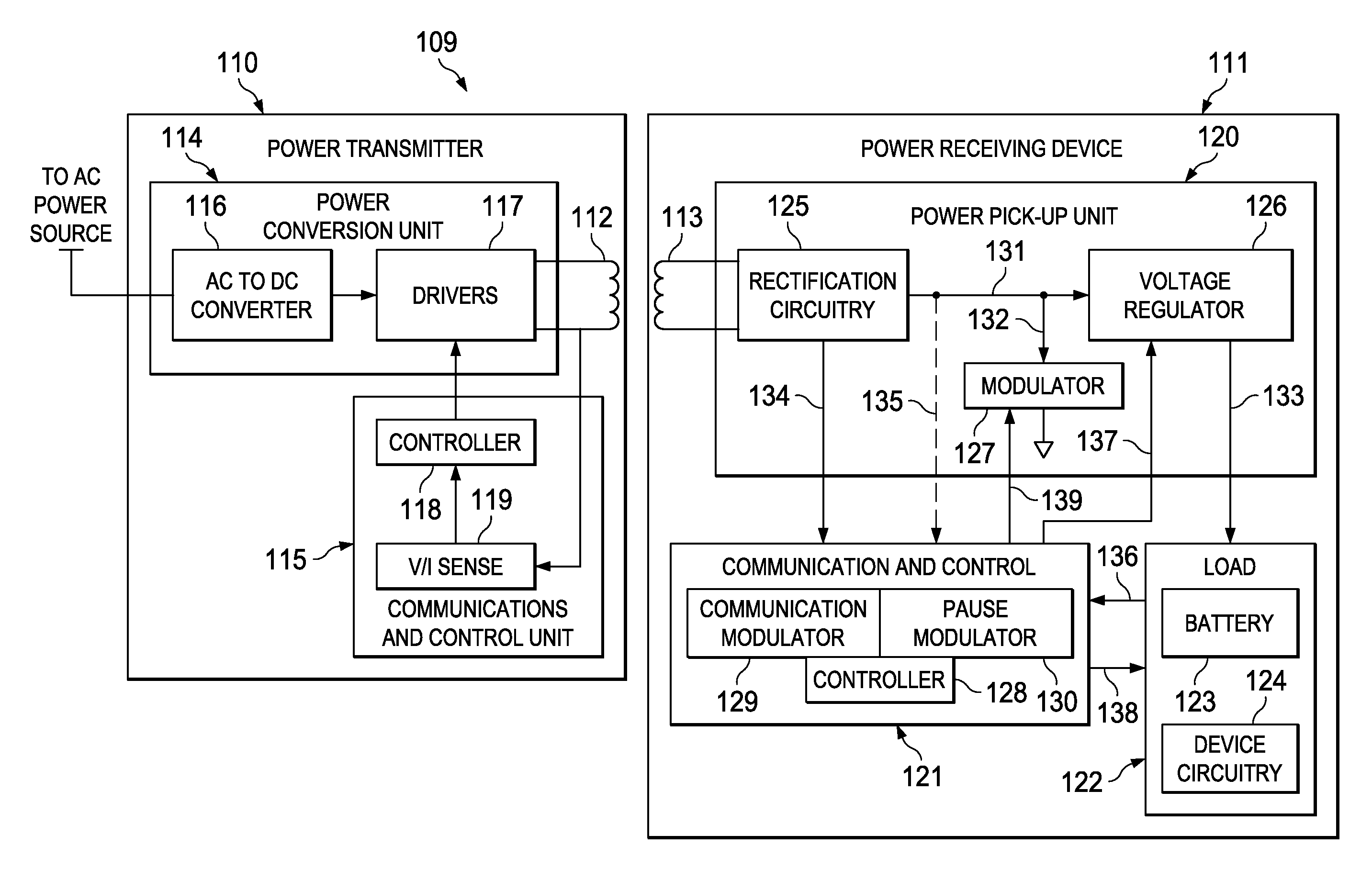
[0025]An example wireless power transfer system 109 incorporating an embodiment of the present invention is shown in FIG. 4. The wireless power transfer system 109 generally includes a power transmitter 110 and a power receiving device 111. The power receiving device 111 may be any appropriate electronic device, such as a cell phone, game controller, electric toothbrush, clock, computer, microphone, etc. Electrical power is transferred from a primary inductor coil 112 in the power transmitter 110 to a secondary inductor coil 113 in the power receiving device 111 by means of electromagnetic field coupling. During communication time periods, the power receiving device 111 modulates the electromagnetic field between first and second states in a manner that can be detected by the power transmitter 110 as logic bits in a communication bit stream. As described in more detail below, the power receiving device 111 continues to modulate the electromagnetic field between the same states (or w...


PUM


Abstract

A wireless power receiver receives electrical power via electromagnetic field coupling from a wireless power transmitter. During communication time periods, the power receiver alters the electromagnetic field in a manner that the power transmitter can detect as a string of logic bits in a communication bit stream for sending data to the power transmitter. During pause time periods when data is not being sent to the power transmitter, the power receiver alters the electromagnetic field in a manner that the power transmitter does not detect as a string of logic bits (e.g. at a rate outside a communication frequency band). In some embodiments, a ripple is reduced in a voltage produced by the wireless power receiver from the electromagnetic field during the communication and pause time periods.

Description

BACKGROUND OF THE INVENTION[0001]Wireless power transfer is generally achieved by electromagnetic field coupling between a power transmitter and a power receiver. A primary electromagnetic field coupling component in the power transmitter generates an electromagnetic field that is picked up by a secondary electromagnetic field coupling component in the power receiver when the power receiver is placed near the power transmitter. The overall power receiving device (containing the power receiver) rectifies, conditions and / or regulates the received power as needed for the functioning of the device.[0002]This power transfer technique is widely used in many electrical devices (typically, but not exclusively, mobile or handheld devices, e.g. cell phones, electric toothbrushes, etc.) for a variety of purposes (e.g. to safely isolate the transmitter from the receiver, to recharge batteries encased within a watertight housing, etc.). The Qi Low Power Specification (System Description, Wireles...

Claims


Application Information

Patent Timeline
IPC IPC(8): H02J17/00
CPCH02J5/005H04B5/0081H04B5/0037H02J7/025H02J7/00036H02J7/00045H02J50/80H02J50/12H04B5/26H04B5/79
Inventor MURATOV, VLADIMIR A.
Owner TEXAS INSTR INC
Features
  • Generate Ideas
  • Intellectual Property
  • Life Sciences
  • Materials
  • Tech Scout
  • Unparalleled Data Quality
  • Higher Quality Content
  • 60% Fewer Hallucinations
Learn More