Gas turbine outer case active ambient cooling including air exhaust into a sub-ambient region of exhaust flow

a technology of active ambient cooling and gas turbines, applied in the direction of machines/engines, non-positive displacement fluid engines, pumps, etc., can solve the problems of increasing the stress in the case, increasing the temperature, and increasing the deformation of the outer cas

Inactive Publication Date: 2013-06-13
SIEMENS AG
View PDF22 Cites 27 Cited by
  • Summary
  • Abstract
  • Description
  • Claims
  • Application Information

AI Technical Summary

Benefits of technology

[0008]The exit structure may produce a jet pump effect at the air duct outlet end to produce a sub-ambient pressure within the air duct and draw heated cooling air from the cooling channel into the air duct.
[0021]The exit shield diverts flow of exhaust gas in the exhaust manifold away from the manifold opening and effects the reduced pressure at the outlet end of the air duct.

Problems solved by technology

Advancements in gas turbine engine technology have resulted in increasing temperatures, and associated outer case deformation due to thermal expansion.
Case deformation may increase stresses in the case and in components supported on the case within the engine, such as bearing support struts.
The additional stress, which may operate in combination with low cycle fatigue, may contribute to cracks, fractures or failures of the bearing support struts that are mounted to the casing for supporting an exhaust end bearing housing.

Method used


Image

  • Gas turbine outer case active ambient cooling including air exhaust into a sub-ambient region of exhaust flow
  • Gas turbine outer case active ambient cooling including air exhaust into a sub-ambient region of exhaust flow
  • Gas turbine outer case active ambient cooling including air exhaust into a sub-ambient region of exhaust flow

Examples


Embodiment Construction

[0039]In the following detailed description of the preferred embodiment, reference is made to the accompanying drawings that form a part hereof, and in which is shown by way of illustration, and not by way of limitation, a specific preferred embodiment in which the invention may be practiced. It is to be understood that other embodiments may be utilized and that changes may be made without departing from the spirit and scope of the present invention.

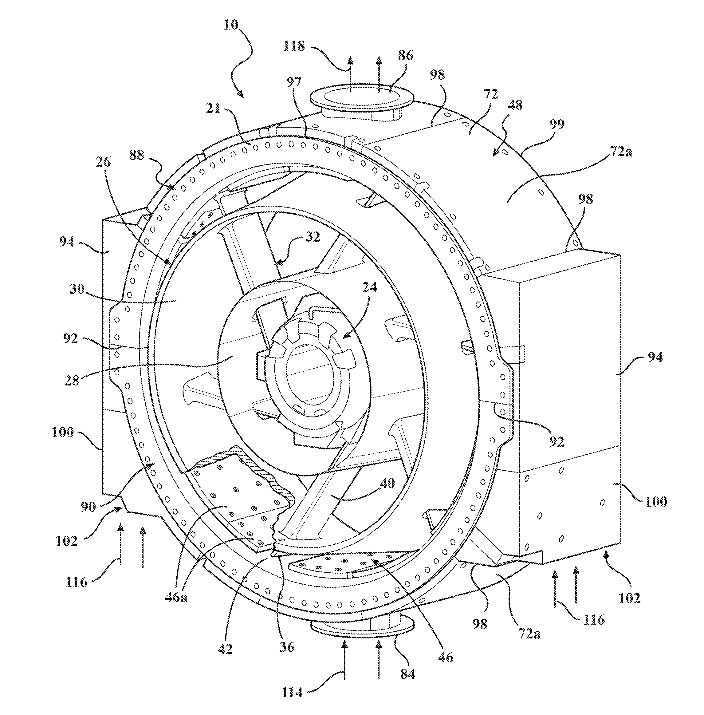
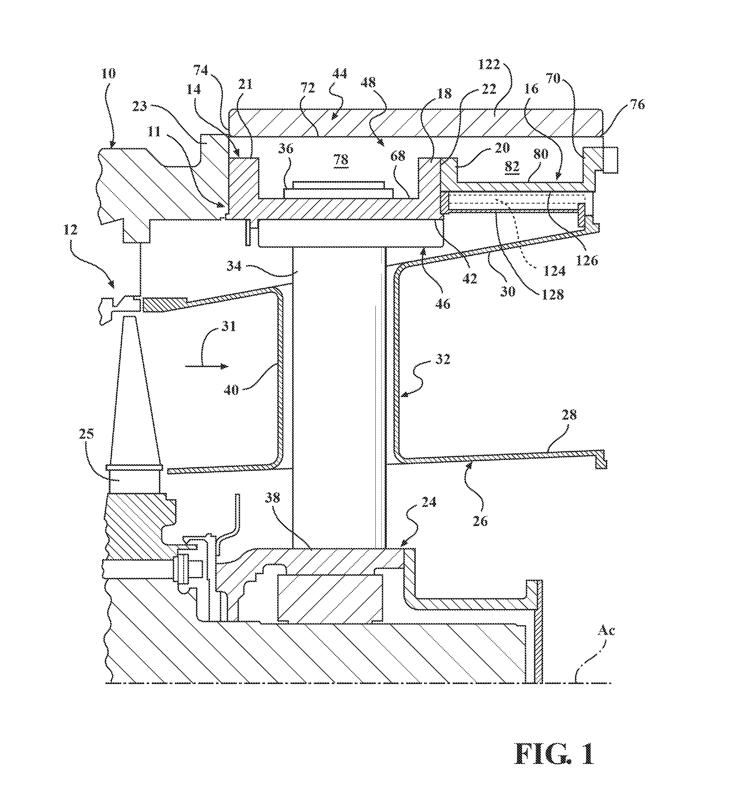
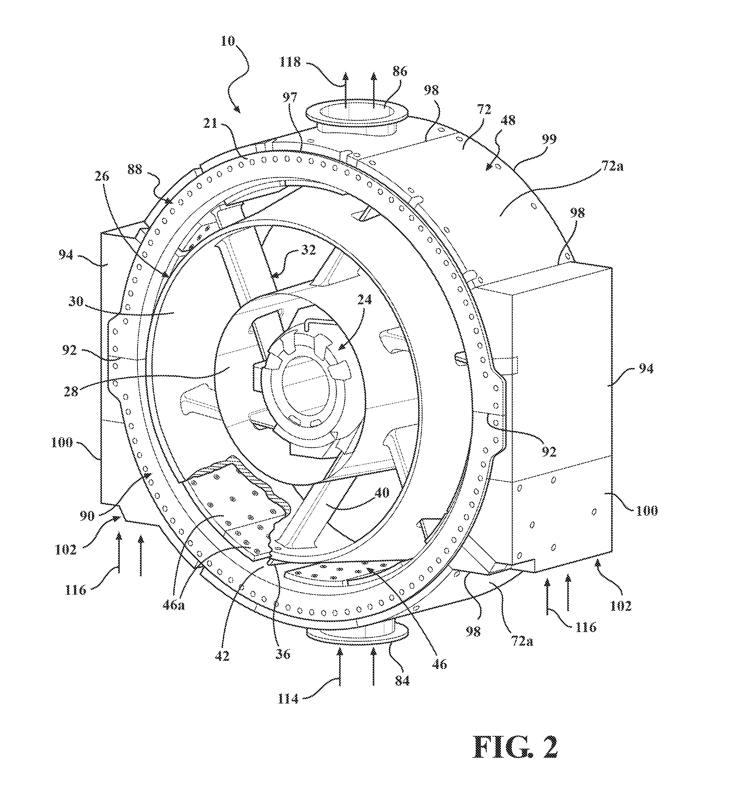
[0040]Referring to FIG. 1, a portion of an exhaust section 10 of a gas turbine engine is shown located axially downstream from a turbine section 12 to illustrate aspects of the present invention. The exhaust section 10 generally comprises a cylindrical structure comprising an outer case 11 extending circumferentially around a generally horizontal central longitudinal axis AC and forms a downstream extension of an outer case the gas turbine engine. The outer case 11 of the exhaust section 10 includes an exhaust cylinder or turbine exhaust...


PUM


Abstract

A gas turbine engine including an outer case extending circumferentially around the central longitudinal axis. A cooling channel is associated with the outer surface of the outer case, the cooling channel having a channel inlet and a channel outlet. An air duct is provided including an inlet end in fluid communication with the channel outlet and an outlet end in fluid communication with an exhaust gas flow from a turbine section of the gas turbine engine. An exit structure is located at the air duct outlet end, and the exit structure provides a sub-ambient pressure at the air duct outlet end to induce a flow from the air duct inlet end to the air duct outlet end.

Description

CROSS-REFERENCE TO RELATED APPLICATIONS[0001]This application is a continuation-in-part of and claims priority to U.S. patent application Ser. No. 13 / 314,311, filed Dec. 8, 2011, which application is herein incorporated by reference in its entirety as if fully set forth herein.FIELD OF THE INVENTION[0002]The present invention relates to gas turbine engines and, more particularly, to structures for providing thermal protection to limit heating of the outer case of a gas turbine engine.BACKGROUND OF THE INVENTION[0003]A gas turbine engine generally includes a compressor section, a combustor section, a turbine section and an exhaust section. In operation, the compressor section may induct ambient air and compress it. The compressed air from the compressor section enters one or more combustors in the combustor section. The compressed air is mixed with the fuel in the combustors, and the air-fuel mixture can be burned in the combustors to form a hot working gas. The hot working gas is ro...

Claims


Application Information

Patent Timeline
Patent Type & Authority Applications(United States)
IPC IPC(8): F01D25/12
CPCF01D25/12F05D2260/202F01D25/305F01D9/065
Inventor MUNSHI, MRINALFINNERAN, JOHN W.SHTEYMAN, YEVGENIYGRABER, DARYL J.PORTER, MATTHEW R.LEAGON, JONATHAN M.
Owner SIEMENS AG
Why Eureka
Try Eureka