Variable geometry turbocharger

a turbocharger and variable geometry technology, applied in the direction of machines/engines, stators, liquid fuel engines, etc., can solve the problems of degrading turbine efficiency, limited, difficult to achieve enhancing turbine efficiency, etc., and achieve the effect of simple structure and guaranteed stable movement of nozzle vanes

Inactive Publication Date: 2013-06-13
IHI CORP
View PDF1 Cites 14 Cited by
  • Summary
  • Abstract
  • Description
  • Claims
  • Application Information

AI Technical Summary

Benefits of technology

[0021]According to the variable geometry turbocharger of the invention, the front and rear exhaust introduction walls are disk-shaped and the disk-shaped rear exhaust introduction wall is fitted to and disposed, with the space, in the shoulder formed on the turbine housing. Thus, an excellent effect can be achieved such that, with a simple structure, the deformation of the front and rear exhaust introduction walls in a non-diametral direction can be prevented and stable movement of the nozzle vanes can be ensured.

Problems solved by technology

However, it has turned out that substantially enhancing turbine efficiency is difficult to attain and is limited even if the sealing device 23 is elaborately configured.
Thus, findings have been obtained such that the exhaust gas with higher pressure flows downstream of the exhaust nozzle 9 through the clearance between each nozzle vane 15 and the rear exhaust introduction wall 11 and significantly disturbs the exhaust gas at the turbine impeller 4 outlet, leading to degraded turbine efficiency.

Method used


Image

  • Variable geometry turbocharger
  • Variable geometry turbocharger
  • Variable geometry turbocharger

Examples


Embodiment Construction

[0029]Embodiments of the invention will be described below with reference to the attached drawings.

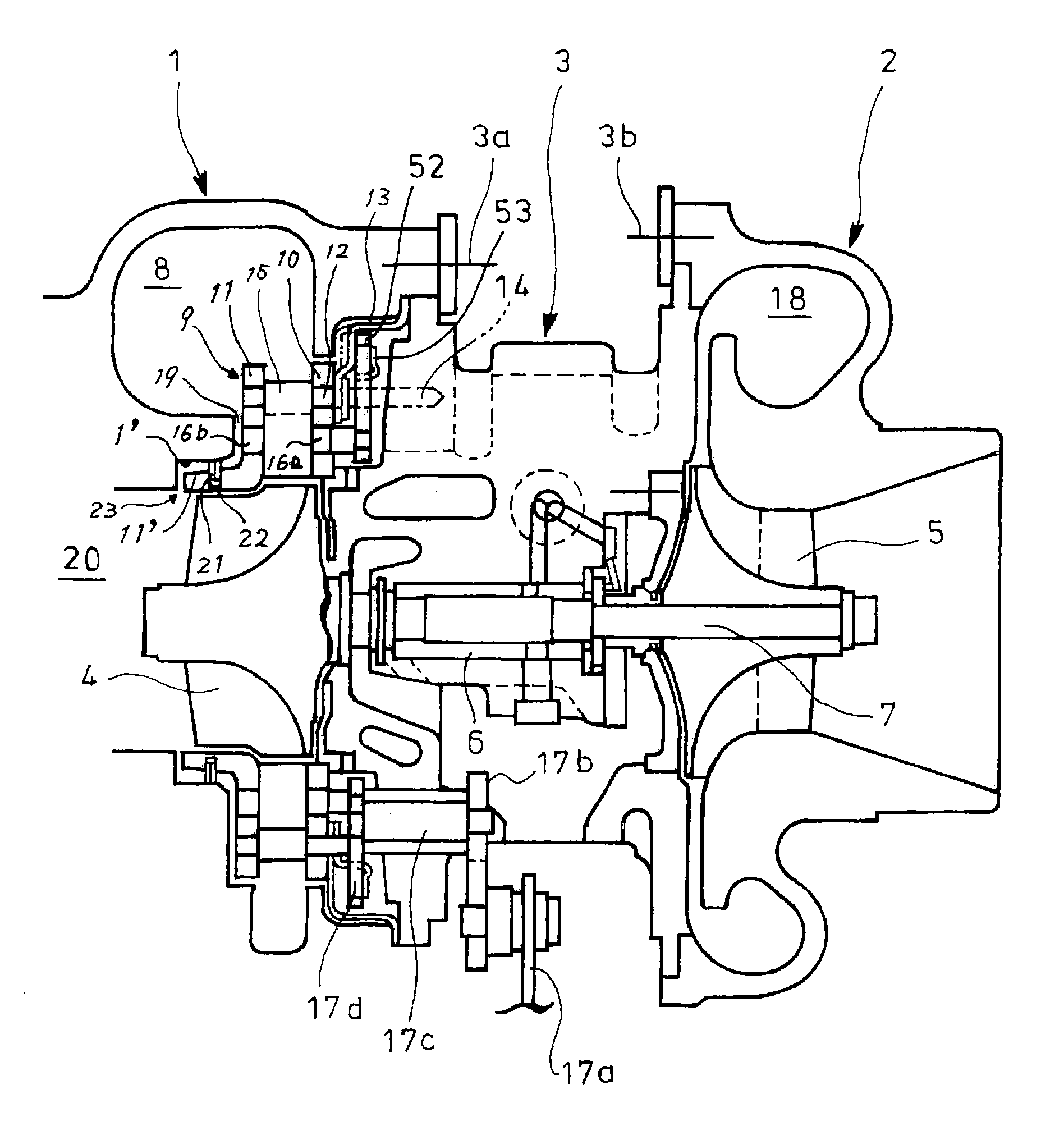
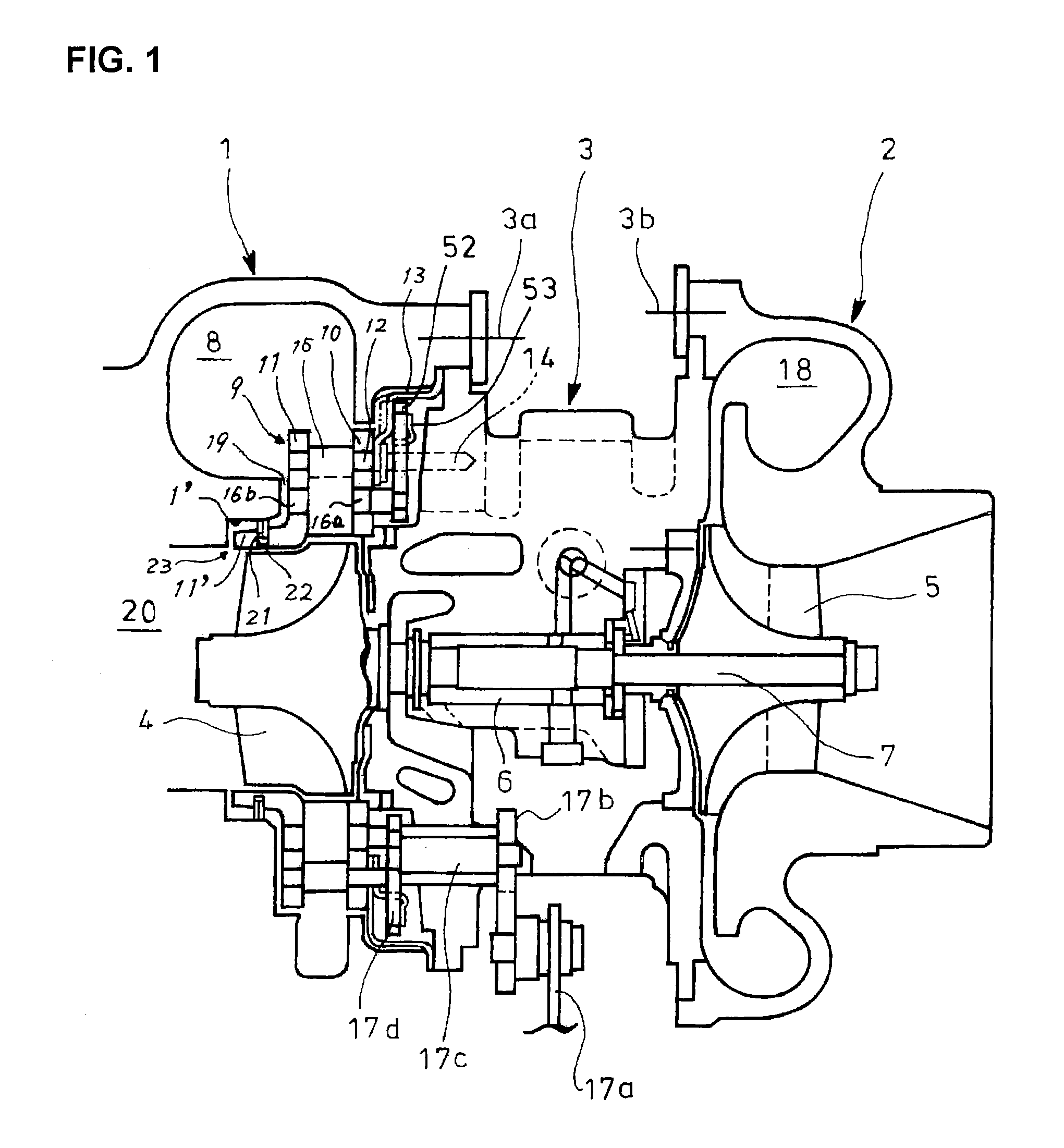
[0030]FIG. 2 shows an embodiment of the invention in which a disk-shaped rear exhaust introduction wall 51 is substituted for the rear exhaust introduction wall 11 with the extension 11′ in the variable geometry turbocharger of FIG. 1. Thus, each of the front and rear exhaust introduction walls 10 and 51 is disk-shaped. It is preferable that the disk-shaped front and rear exhaust introduction walls 10 and 51 are made of same material or materials equivalent in linear expansion coefficient. With the rear and front exhaust introduction walls 51 and 10 set equivalent in linear expansion coefficient, the vane shafts 16a and 16b fixed to opposite sides of each nozzle vane 15 are consistently coaxially supported by the exhaust introduction walls 51 and 10.

[0031]The turbine housing 1 is formed with an extension 39 extending to a position facing to and spaced apart by a required space from the...


PUM


Abstract

An exhaust nozzle 9 has nozzle vanes 15 interposed between front and rear exhaust introduction walls 10 and 51. A space 19 is between the wall 51 and a turbine housing 1. A sealing device 25 is arranged upstream, in a direction of exhaust gas, of each through hole 24 provided in the wall 51 for penetration of a vane shaft 16a to prevent exhaust gas in a scroll passage 8 from leaking through the space 19 to a turbine impeller 4. Each of the walls 10 and 51 is disk-shaped, the turbine housing 1 being formed with a shoulder 50 to which the wall 51 is fitted with the space 19.

Description

TECHNICAL FIELD [0001]The present invention relates to a variable geometry turbocharger capable of enhancing turbine efficiency and enabling a smooth operation of nozzle vanes with a simple structure.BACKGROUND ART [0002]FIG. 1 is a longitudinal sectional view showing an overall structure of a variable geometry turbocharger to which the present invention is applied. In the turbocharger, turbine and compressor housings 1 and 2 are integrally assembled via a bearing housing 3 by fastening bolts 3a and 3b. Turbine and compressor impellers 4 and 5 disposed in the turbine and compressor housings 1 and 2, respectively, are coupled together by a turbine shaft 7 rotatably supported via a bearing 6 in the bearing housing 3.[0003]The bearing housing 3 is provided, on its side adjacent to the turbine housing, with an exhaust nozzle 9 for guiding exhaust gas introduced into a scroll passage 8 in the turbine housing 1 to the turbine impeller 4.[0004]The exhaust nozzle 9 comprises a front and rea...

Claims


Application Information

Patent Timeline
Patent Type & Authority Applications(United States)
IPC IPC(8): F01D25/24
CPCF02B37/24F01D17/162F01D25/24F05D2240/58F05D2220/40F01D17/165F02B39/00
Inventor MATSUYAMA, YOSHIMITSUINOUE, TOMOHIROSAKAI, YASUTAKA
Owner IHI CORP
Why Eureka
Try Eureka