System for anchoring a load

a load and system technology, applied in the field of anchoring systems, can solve the problems of limited current ground anchoring technology, high stress on the anchoring tendons, and prone to corrosion, and achieve the effect of increasing the load transfer capacity of the anchoring tendons with multiple tensile elements

Active Publication Date: 2013-06-20
SINCLAIR
View PDF12 Cites 12 Cited by
  • Summary
  • Abstract
  • Description
  • Claims
  • Application Information

AI Technical Summary

Benefits of technology

[0009]Broadly stated, the invention stems from the recognition that the load transfer capacity of an anchoring tendon with multiple tensile elements may be substantially increased by sequentially tensioning different groups of tensile elements of the tend

Problems solved by technology

However, these anchor tendons were highly stressed and prone to corrosion since under load transfer conditions, horizontal cracking occurs in the anchoring grout (particularly about the intersection of the free and bond length of the anchor) allowing aggressive agents to attack the highly stressed tendon.
However, based on the inside diameter of the corrugated sheath, the ultimate load transfer through the corrugated sheath is limited to around 5.3 MPa using a 35 MPa grout.
Current ground anchoring technology is limited to the use of anchoring tendons comprising 91 strands with a breaking load of approximately 25,400 kN.
There are two particular problems with load t

Method used


Image

  • System for anchoring a load
  • System for anchoring a load
  • System for anchoring a load

Examples


Embodiment Construction

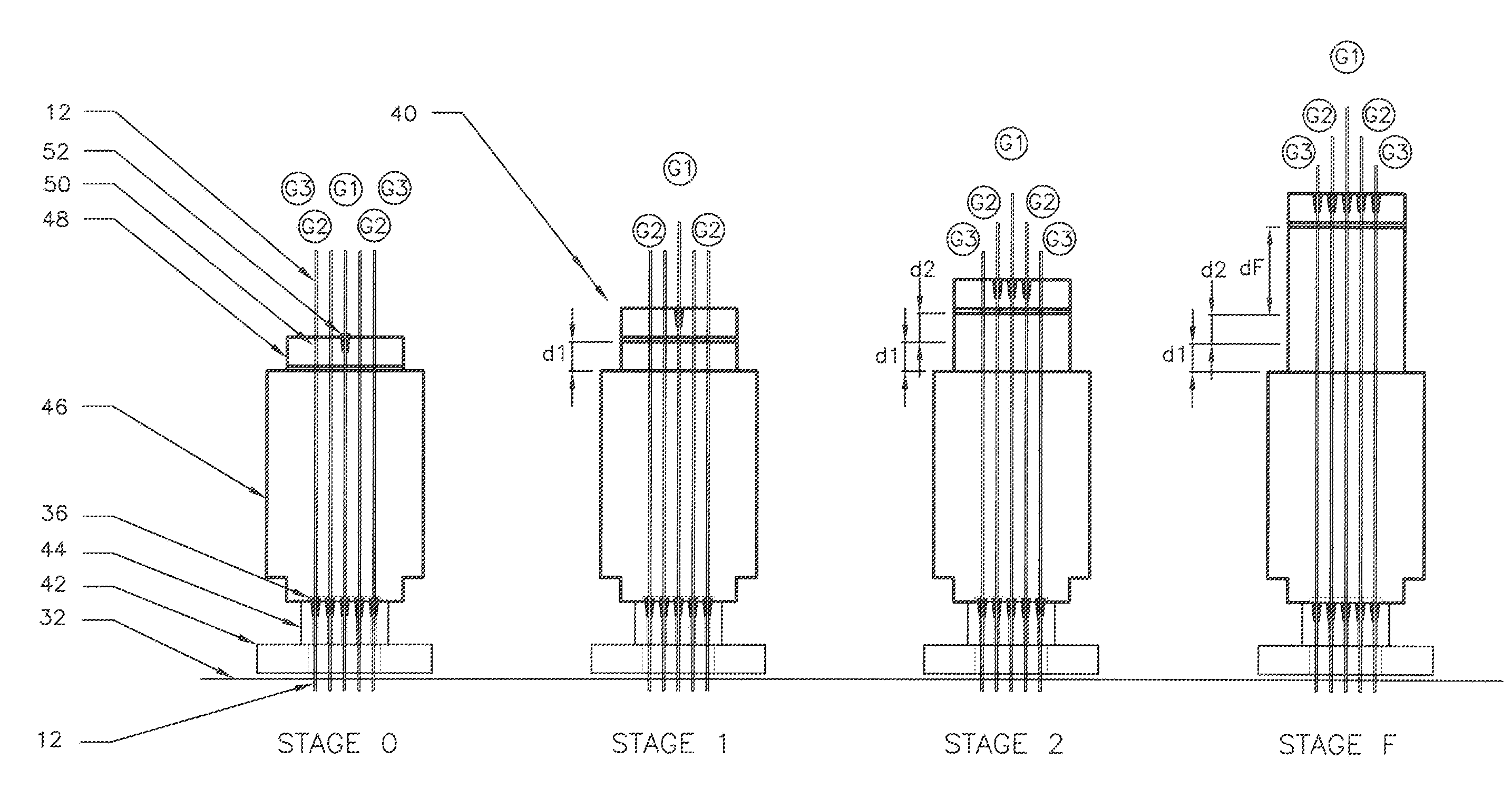
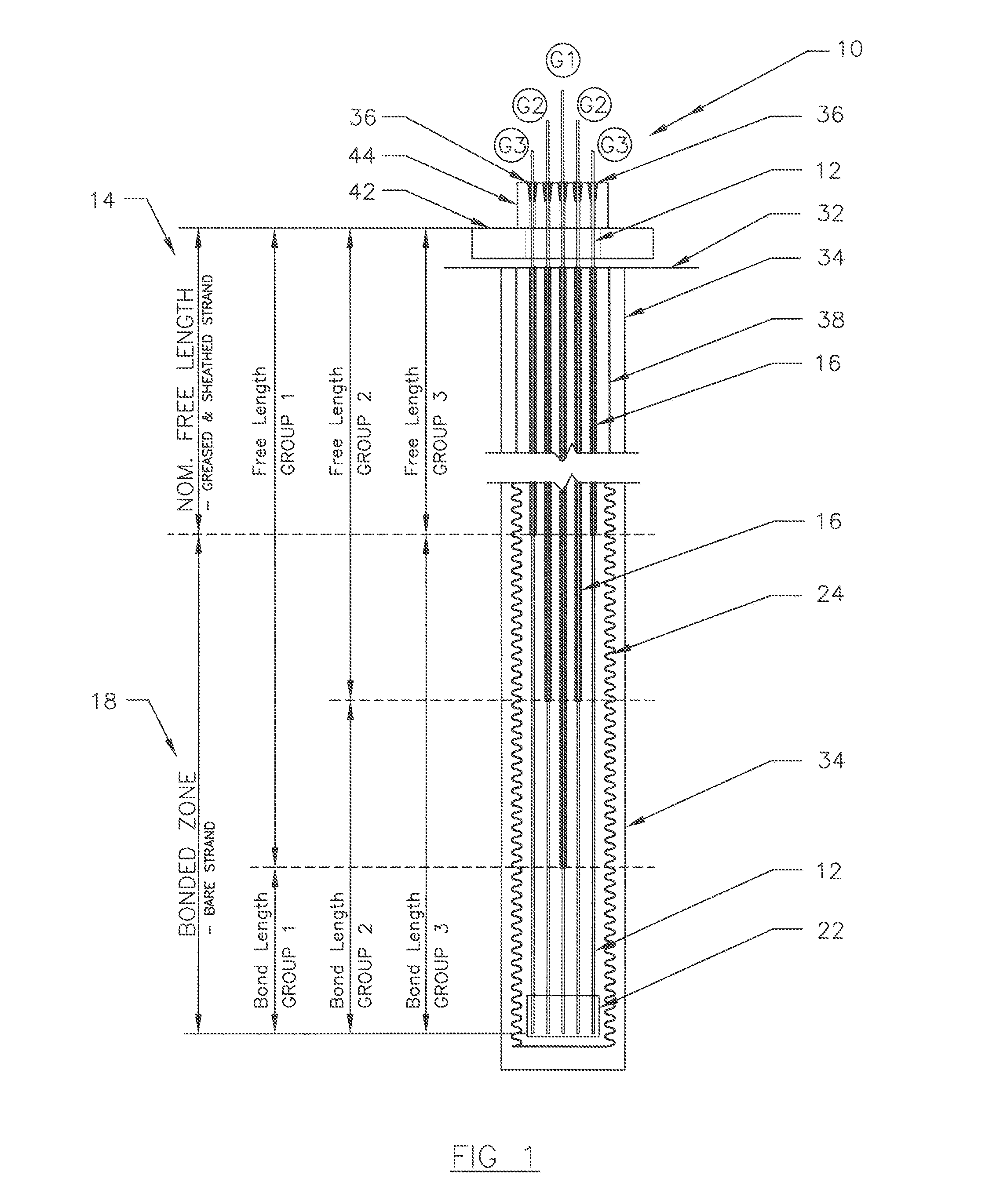
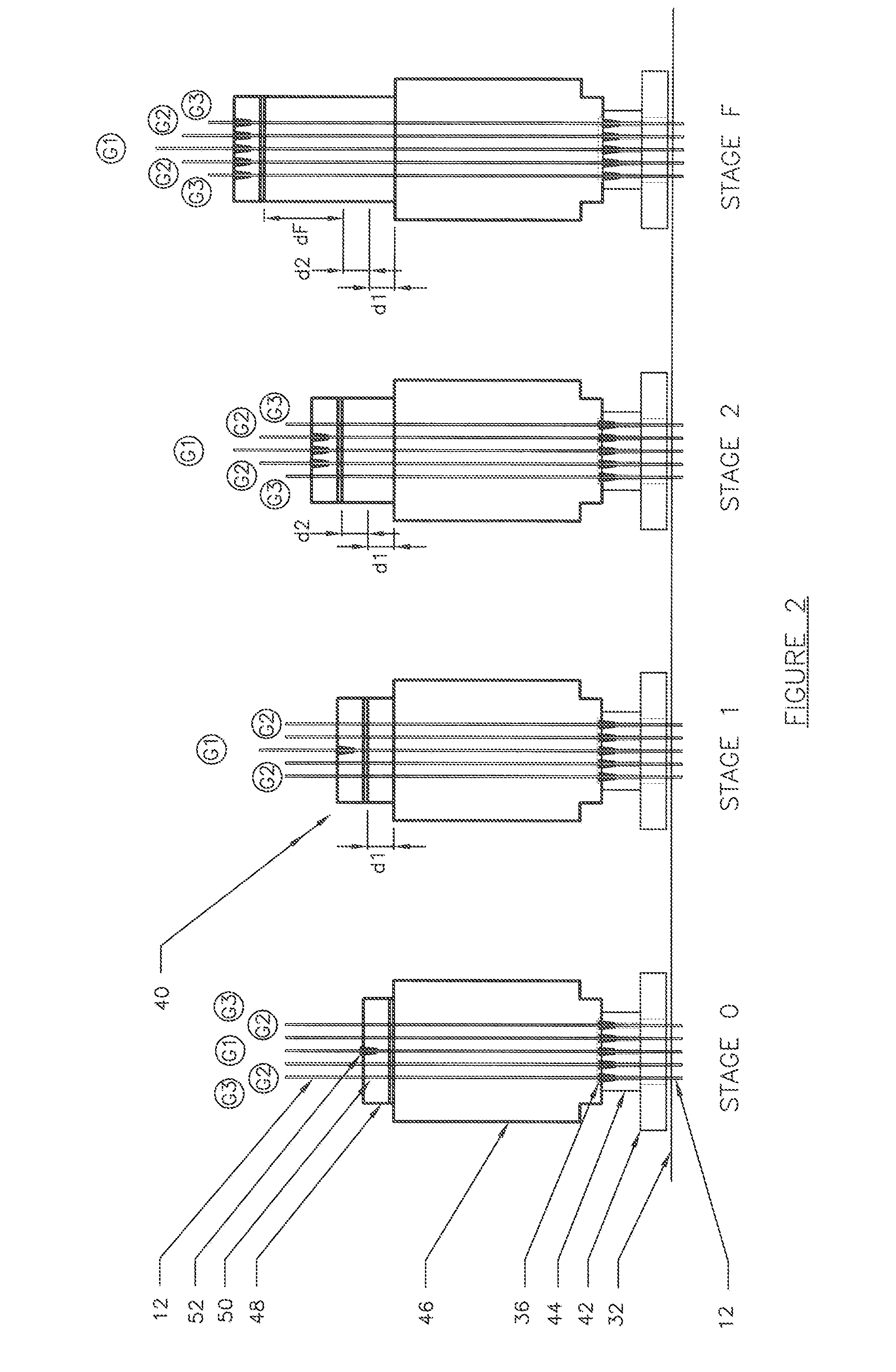
[0044]A unitary anchoring tendon 10 suitable for use in a method embodied by the invention is shown in FIG. 1. The tendon has a plurality of tensile elements in the form of multi-wire steel strands 12 each of which has a free length 14 received within a respective sleeve 16, and a bond length 18. The bond lengths 18 of the strands 12 terminate in the nose of the tendon generally indicated by the numeral 22 and are fixed together in the tendon's nose at their leading ends by an epoxy or suitable fixing system. In practice, the nose 22 is generally round ended as conventionally known to assist insertion of the tendon down the corrugated sheath 24 as further described below. The strands 12 of the tendon each comprise a central king wire about which a plurality of outer wires (typically 6) are spirally wound around. A seal (not shown) is located on the end of each sleeve 16 at the transition between the bond length and the free length of respective of the strands to stop entry of water ...


PUM


Abstract

The invention relates to a method for anchoring a load (26) to an anchorage (30) utilising at least one unitary anchoring tendon (10) including a plurality of tensile elements (12) each having a free length (14) and a bond length (18). The tendon is located lengthwise in a bore (34) formed through the load into the anchorage, and different groups (G1, G2, G3) of the strands of the tendon are tensioned in a predetermined sequence to a respective initial displacement length prior to the different groups being collectively tensioned to a respective final displacement length to anchor the load.

Description

FIELD OF THE INVENTION[0001]The present invention in one or more forms relates to anchoring systems and the use of ground anchor(s) to anchor a structure against an applied force and / or provide stability to the structure. The invention has application in civil engineering works with particular, though not exclusive application, to the anchoring of large structures such as concrete dam walls.BACKGROUND OF THE INVENTION[0002]Large capacity permanent rock anchors are typically utilised in civil engineering works to contain large forces, examples of which include bridge restraints and to tie down concrete dams to improve their safety via resistance to overturning or sliding. It was not until about 1980 that improvements in technology allowed large capacity permanent anchors to be considered a long term viable option for high load applications, with ground anchors having capacities of about 10,500 kN UTS then 13,750 kN UTS being developed. However, these anchor tendons were highly stress...

Claims


Application Information

Patent Timeline
IPC IPC(8): E02D5/74E04G21/00
CPCE01D22/00E02D5/74E04G21/00E02D27/50E02D5/76
Inventor SINCLAIR, MARK RONALD
Owner SINCLAIR
Why Eureka
Try Eureka