Light Emitting System

a technology of led lighting and diodes, which is applied in the field of led lighting assemblies, can solve the problems of complex heat generation pathways, high cost and difficulty in manufacturing, and high complexity of typical led lighting devices

Inactive Publication Date: 2013-06-20
ONCE INNOVATIONS
View PDF2 Cites 36 Cited by
  • Summary
  • Abstract
  • Description
  • Claims
  • Application Information

AI Technical Summary

Problems solved by technology

Typical LED lighting devices are complex and therefore expensive and difficult to manufacture.
This is a result of complex circuitry used to power the LEDs that with the LEDs generates excessive amounts of heat.
Thus in existing LED lighting devices, the heat transfer pathway is complex because heat transfer is required for both the LEDs and the LED driving circuitry.
The aluminum is expensive driving the cost to manufacture upwards.
Therefore the heat sink included in a LED light is complex.
In addition, the electronics in existing LED lighting devices are large and generally are mounted on a separate structure (e.g., an assembly or substrate) from the structure supporting the LEDs.
Further, the system for diffusion of the light which can be incorporated within a LED lighting device is difficult and inefficient to produce.
Another problem with current LED lighting devices is the cost of components and inventory management of bulbs having different wattage ratings is high.
As a result, such lights bulbs having different wattage ratings cannot necessarily be produced on a same production line.
Likewise, creating different bulbs require multiple inventory factors.
As a result, separate inventories of lights bulbs of each wattage rating may be needed, resulting in large light bulb inventories.
Another problem exists in current designs where electronics are positioned within or along a heat sink.
A further problem with current LED light assemblies is that in order to be configured to be compatible with standard incandescent light-bulbs and light sockets / figures (such as the Edison A19 bulb, as well as other bulbs), the power must be moved by wires to move and return the current from the base to the electronics.
These design approaches increase costs and manufacturing complexity (connecting wires to both ends and snaking wires up through some cavity from the base to the electronics).

Method used


Image

  • Light Emitting System
  • Light Emitting System
  • Light Emitting System

Examples


Embodiment Construction

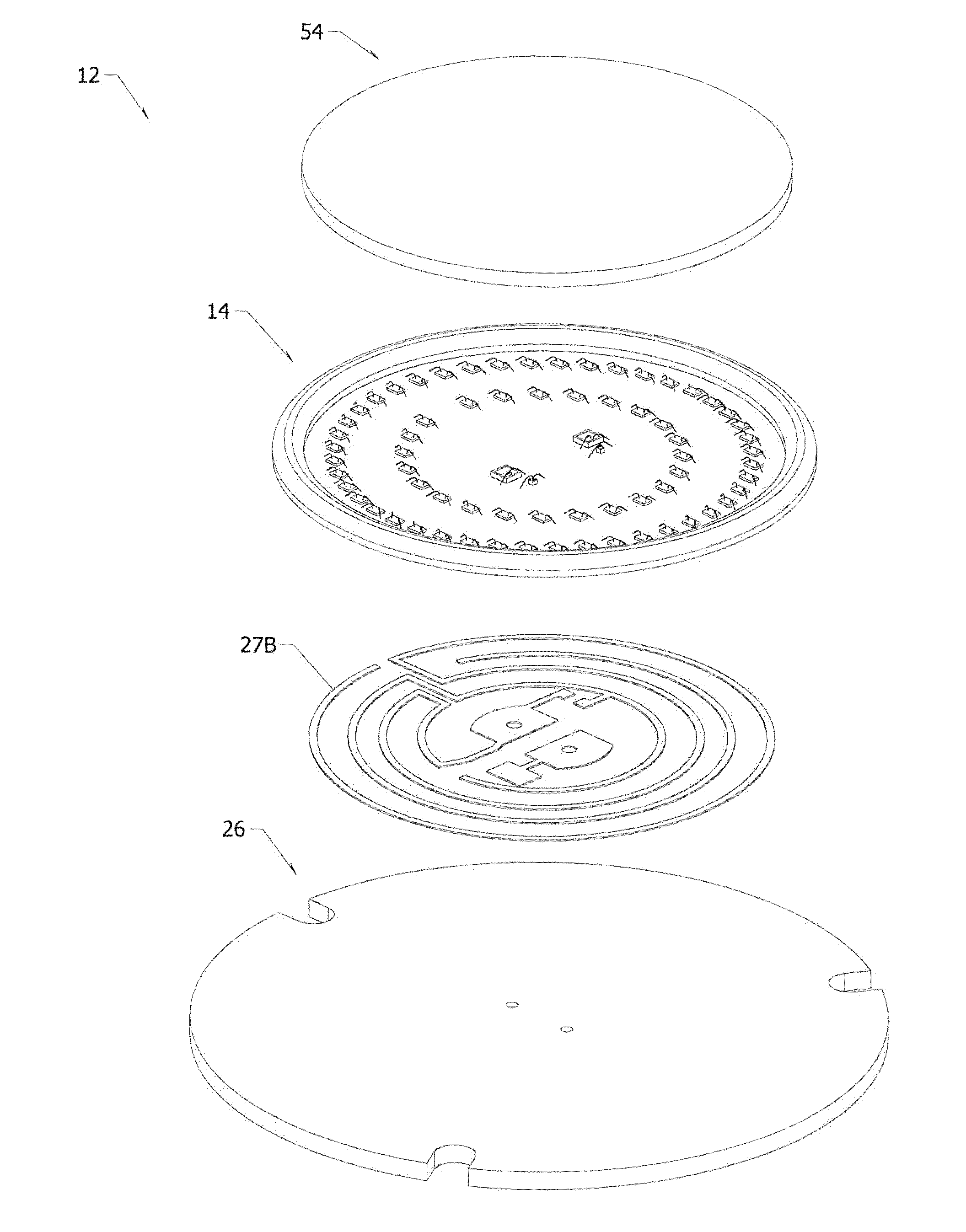
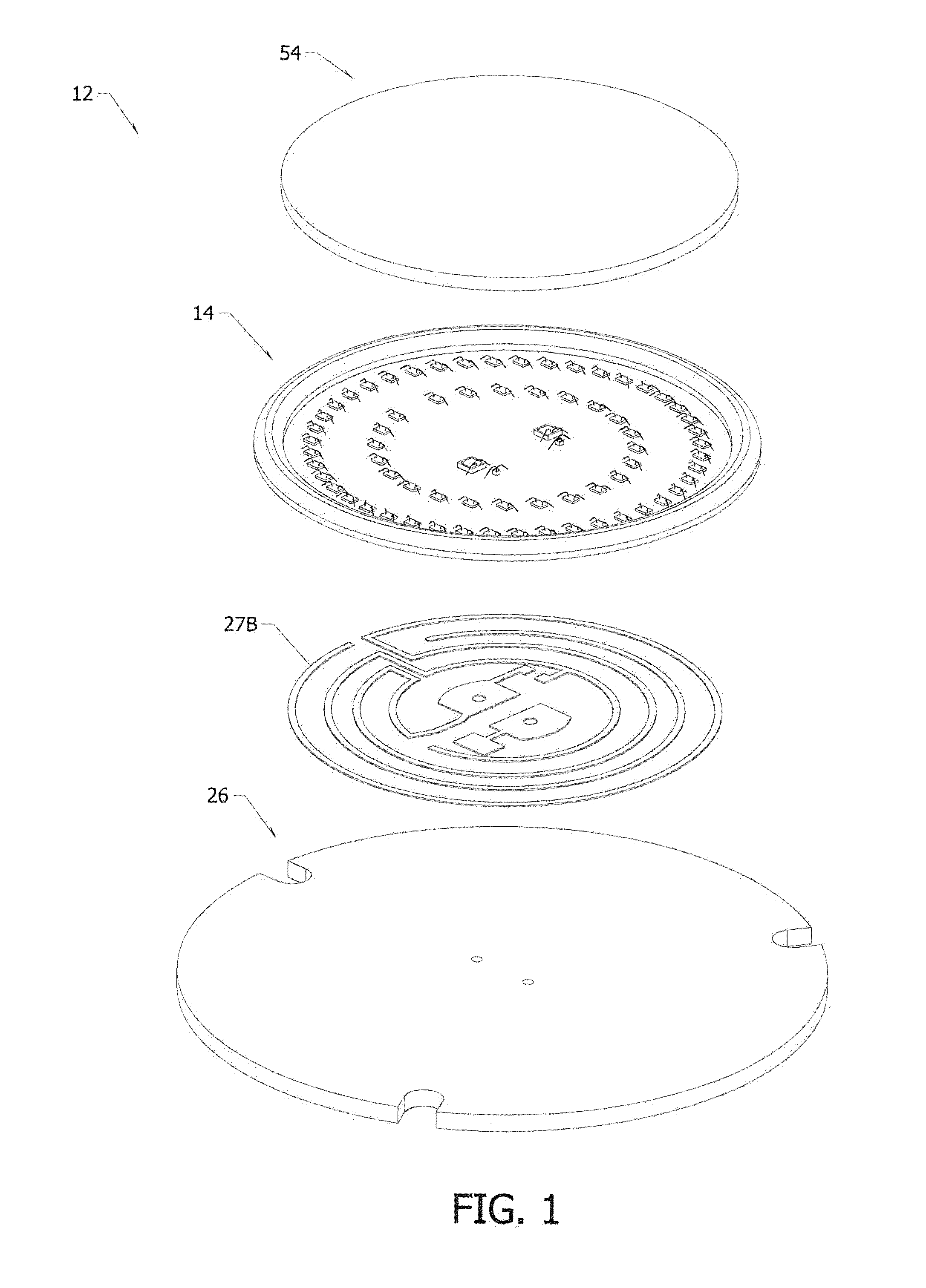
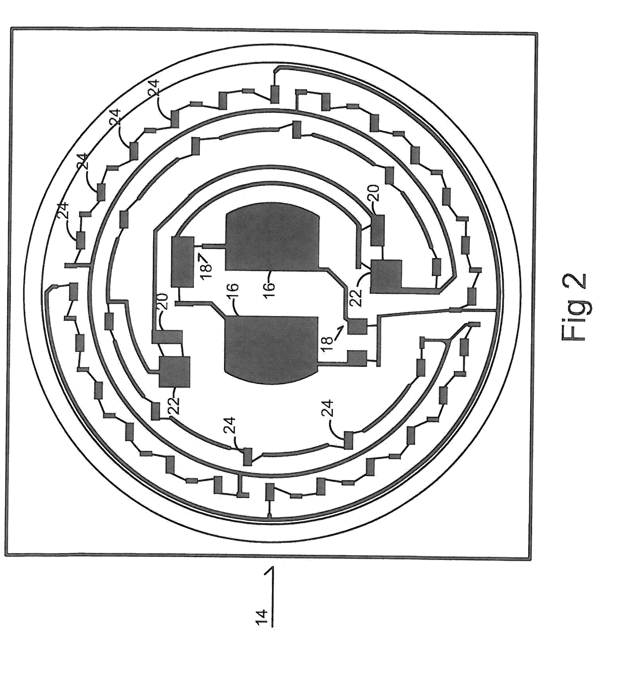
[0021]The figures show a lighting assembly 10 that includes a platform assembly 12 having a common processing engine 14. In one embodiment the common processing engine 14 includes electrical component dies 15 that receive electricity from an AC input 16. In particular a rectifier 18 receives electricity from the AC input 16 and the engine 14 can include protection elements such as a fuse or an MOV and driving elements 20. The driving elements 20 include transistors 22 such as MOSFETs, IGFETs, or the like for powering and dimming a plurality of light emitting diode (LED) dies 24. Further electrical connectors 25 extend from the engine 14 to provide an electrical communication path to other devices.

[0022]The processing engine 14 in one embodiment is formed on a substrate 26 that in one embodiment is a printed circuit board. Alternatively the substrate 26 is a hybrid substrate, or takes the form of other types of electric circuits. The substrate 26 can be any shape or size and in one e...


PUM

PropertyMeasurementUnit
electrically conductiveaaaaaaaaaa
thermal conductionaaaaaaaaaa
heataaaaaaaaaa

Abstract

A light emitting assembly including a substrate having electrically conductive pathways that electrically connect a plurality of electrical component dies. The said electrical components include at least one light emitting diode engaged along the substrate to form an interface surface between the light emitting diode and the substrate. Therefore the combined and unified vector of thermal conduction from the light emitting diode dies are perpendicular to the interface surface when the combined and unified vector of thermal conduction crosses the interface surface from the light emitting diode die to the substrate.

Description

CROSS REFERENCE[0001]This application is a continuation of and based upon U.S. Provisional Patent Application Ser. No. 61 / 570,552 filed Dec. 14, 2011 also entitled LED Lighting Structures and that application is incorporated by reference in full.BACKGROUND OF THE INVENTION[0002]This invention relates to a light emitting diode (LED) lighting assembly. More specifically, this invention relates to an LED lighting assembly that minimizes the components of the lighting structure.[0003]Typical LED lighting devices are complex and therefore expensive and difficult to manufacture. This is a result of complex circuitry used to power the LEDs that with the LEDs generates excessive amounts of heat. Thus in existing LED lighting devices, the heat transfer pathway is complex because heat transfer is required for both the LEDs and the LED driving circuitry. An aluminum heat sink generally handles heat dissipation for multiple heat sources such as from the LED holding mechanism and the AC power ci...

Claims


Application Information

Patent Timeline
Patent Type & Authority Applications(United States)
IPC IPC(8): H01L27/15
CPCA01K61/00A01G33/00H01L2924/13091H01L2224/48091F21V29/58A01K61/005A01K63/06C12M21/02C12M31/10C12N1/12C12N13/00F21S2/00F21V3/0418F21V3/0472F21V23/04F21V23/0442F21V31/00F21Y2101/02F21Y2103/003H01L33/58H01L33/64H01L2924/00014H01L2924/00F21V29/70F21V29/77F21K9/23F21Y2103/10F21Y2115/10F21V3/061F21V3/10H05K1/0203H05K2201/10106Y02A40/81H01L33/647
Inventor GRAJCAR, ZDENKO
Owner ONCE INNOVATIONS
Why Eureka
Try Eureka