
System and method for controlling output ripple of dc-dc converters with leading edge modulation control using current injection

a technology of leading edge modulation and output ripple, which is applied in the direction of dc-dc conversion, power conversion systems, instruments, etc., can solve the problems of unstable operating point of boost and buck-boost converters, nonlinear operation of control loops, and difficult control of the system under these nonlinear effects

Active Publication Date: 2013-06-20
CIRASYS +1
View PDF7 Cites 4 Cited by
  • Summary
  • Abstract
  • Description
  • Claims
  • Application Information

AI Technical Summary

Benefits of technology

The present disclosure is about a voltage converter controlled by an adjusted output voltage which takes into account the inductor current ripple in the voltage converter circuit. This results in a more accurate and stable control of the output voltage. The adjusted output voltage is determined based on the input voltage, the output voltage, and the inductor current through an inductor. The duty ratio of the control signal is determined based on the adjusted output voltage, input voltage, desired output voltage, and a gain factor. The voltage converter circuit can be a boost converter, buck-boost converter, or buck converter. The technical effect of this disclosure is to provide a more accurate and stable control of the output voltage of the voltage converter circuit.

Problems solved by technology

Switching from one state to another and the accompanying nonlinearity of the system causes problems.
But, control of the system under these nonlinear effects becomes difficult when certain performance objectives must be met.
However, use of this method requires making several assumptions, one of them being so-called “small signal operation.” This works well for asymptotic stability in the neighborhood of the operating point, but ignores large signal effects which can result in nonlinear operation of the control loop when, for example, an amplifier saturates during startup, or during transient modes, such as load or input voltage changes.
Unstable zero dynamics associated with TEM with switch on-time sampling in the continuous conduction mode (“CCM”) prevent the use of an input-output feedback linearization because it would result in an unstable operating point for boost and buck-boost converters.
This makes control design extremely difficult.

Method used


Image

  • System and method for controlling output ripple of dc-dc converters with leading edge modulation control using current injection
  • System and method for controlling output ripple of dc-dc converters with leading edge modulation control using current injection
  • System and method for controlling output ripple of dc-dc converters with leading edge modulation control using current injection

Examples


Embodiment Construction

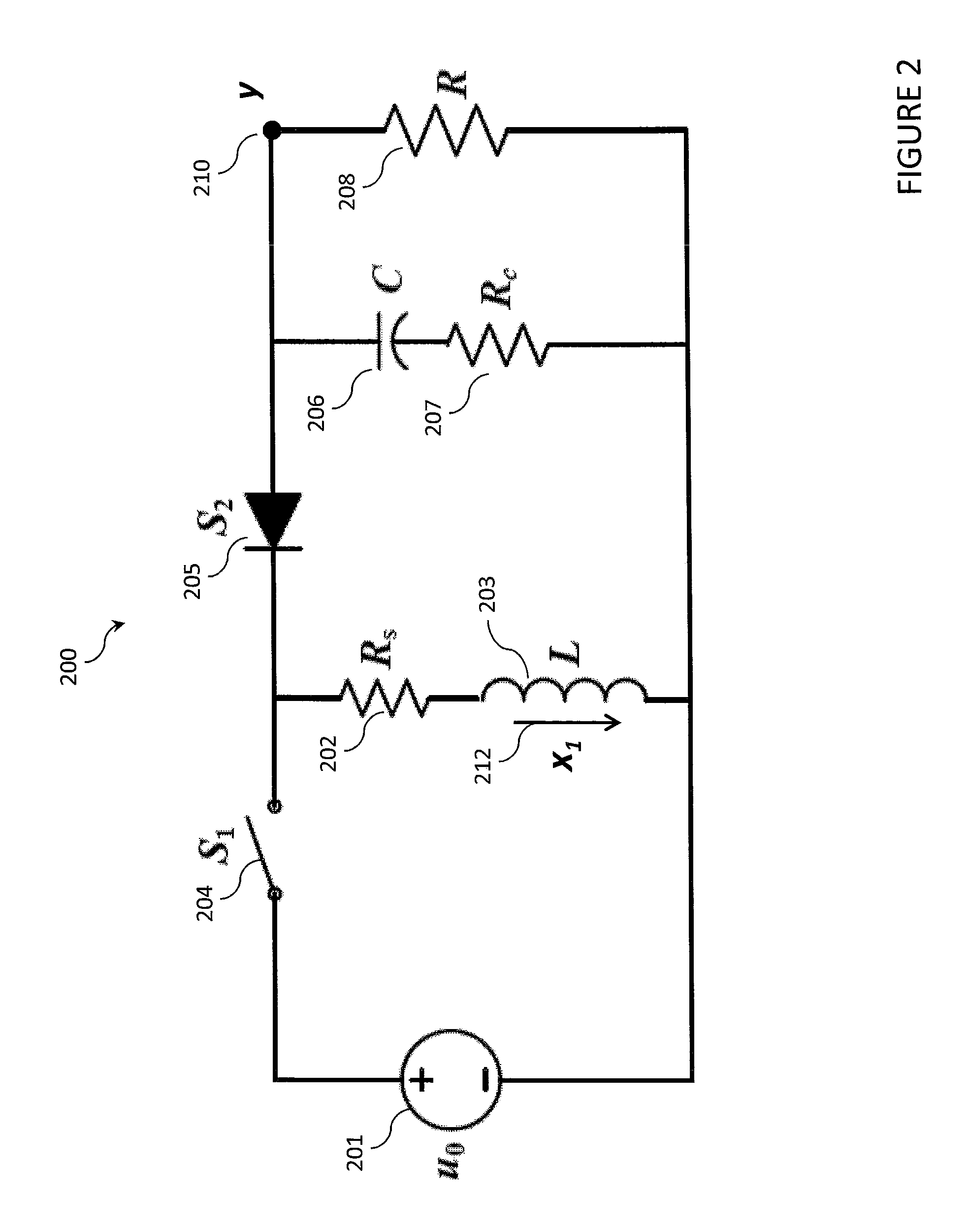
[0021]In the disclosed embodiments of a boost and a buck-boost converter with PWM control, the inductor current is measured and a difference current is formed between the measured inductor current and a measured output current. The difference current represents an inductor current ripple, which is further scaled and then injected into the converter state equations. A method for altering the converter state equations based on inductor current ripple is disclosed.

[0022]In a preferred embodiment, the method of the present disclosure can be used to alleviate dependence on the value of output capacitor equivalent series resistance (“ESR”) (Rc) when used with leading edge modulation (“LEM”) and switch off time sampling in either analog or digital converter systems.

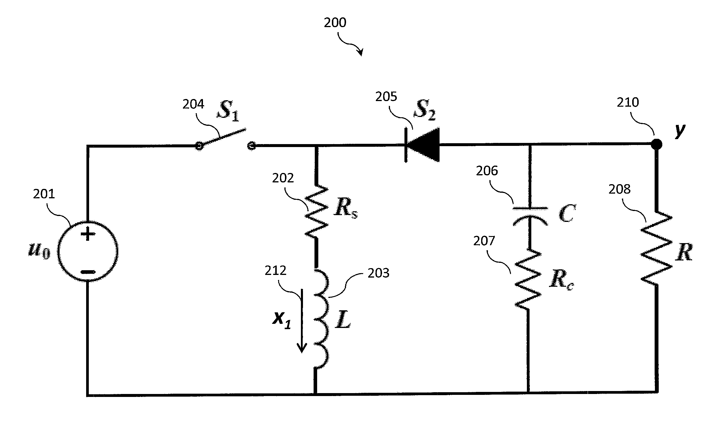
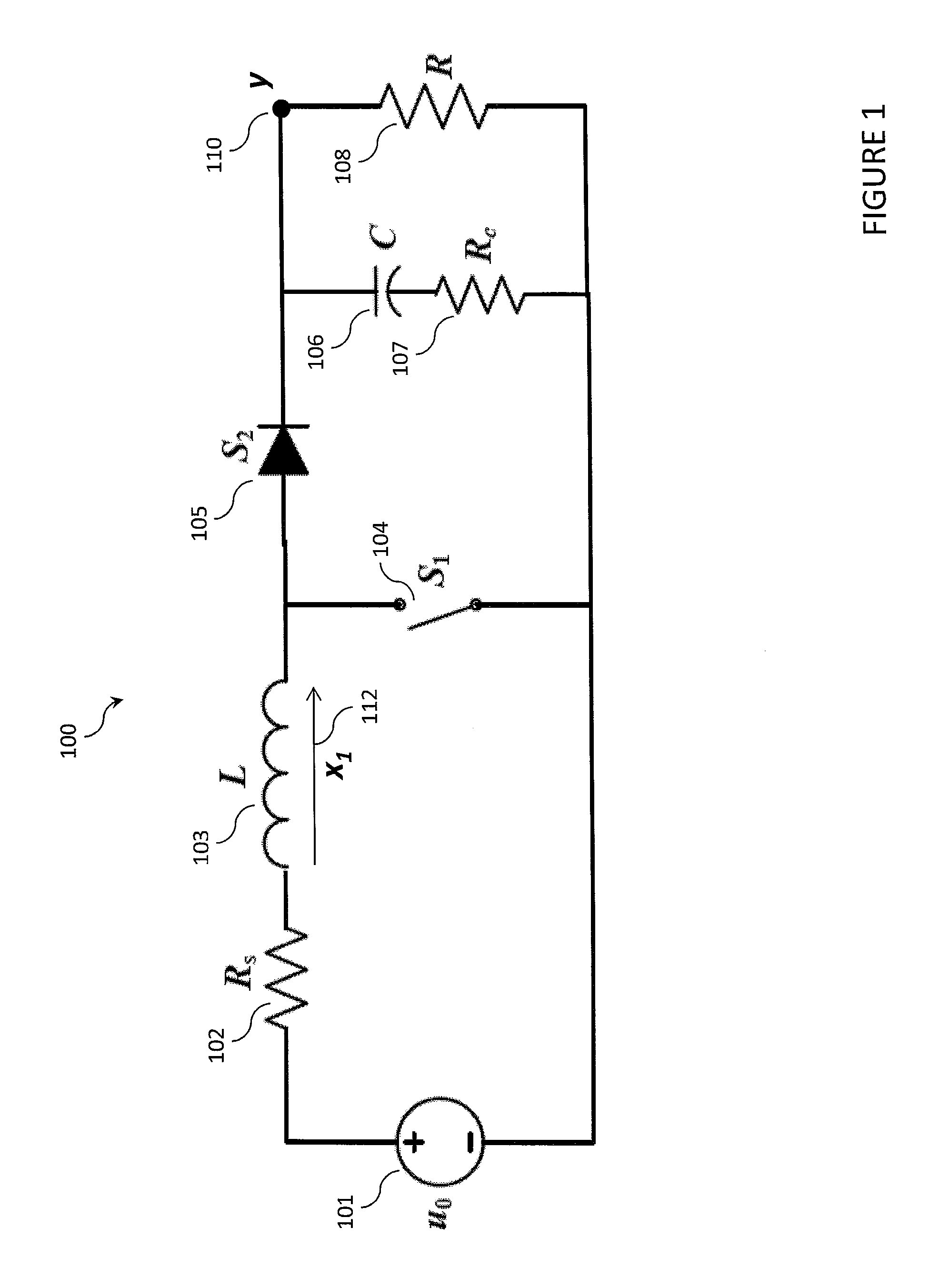
[0023]FIG. 1 illustrates a preferred embodiment boost converter circuit 100 having a single output voltage 110 (y). The boost converter comprises a series resistor 102 (Rs) connected in series with an inductor 103 (L), a switch ...


PUM


Abstract

In a preferred embodiment, a voltage converter comprises a voltage converter circuit, an output adjuster and a controller. The controller provides a control signal at a duty ratio determined dynamically by a set of input signals. The dynamic output adjuster determines the set of input signals by adjusting the ac component of an output voltage based on a gain Q. The dynamic output adjuster alleviates dependence on the value of Rc under leading edge modulation in either analog or digital converter systems. In addition to delivering the desired left half plane zero effects, dynamic output adjustment reduces the value of the output ripple. As a result, modern control methods such as input-output linearization can be used to design both boost and buck-boost PWM converters if only left half plane zero effects are present.

Description

CROSS-REFERENCE TO RELATED APPLICATIONS[0001]This application claims priority benefit from U.S. Provisional Patent Application No. 61 / 578,137 filed Dec. 20, 2011.FIELD OF THE INVENTION[0002]The present invention relates generally to providing modulation signals to electrical circuits and, more particularly, to a system and method for controlling output ripple of DC / DC converters with leading edge modulation (“LEM”) control.BACKGROUND OF THE INVENTION[0003]Power converters are used to convert one form of energy to another (e.g., AC to AC, AC to DC, DC to AC, and DC to DC) thereby making it usable to the end equipment, such as computers, automobiles, electronics, telecommunications, space systems and satellites, and motors. Every application of power electronics involves some aspect of control. Converters are typically identified by their capability and / or configurations, such as, buck converters, boost converters, buck-boost converters, boost-buck converters (uk), etc. For example, D...

Claims


Application Information

Patent Timeline
IPC IPC(8): G05F1/46
CPCG05F1/468H02M1/14H02M3/156H02M3/157H03K7/08H02M1/0025
Inventor TAYLOR, ROBERT JEWELLHUNT, LOUIS R.PADUVALLI, VIKAS V.
Owner CIRASYS
Learn More