Rendering device and rendering method

a rendering device and rendering method technology, applied in the field of rendering devices, can solve the problems of increasing cost and undesirable memory bandwidth, and achieve the effects of reducing memory bandwidth and memory amount required to store image objects, improving rendering responsiveness, and reducing memory bandwidth

Inactive Publication Date: 2013-06-20
PANASONIC INTELLECTUAL PROPERTY MANAGEMENT CO LTD
View PDF12 Cites 9 Cited by
  • Summary
  • Abstract
  • Description
  • Claims
  • Application Information

AI Technical Summary

Benefits of technology

[0010]According to the configuration recited above, through scale-down of the image objects by the first scalers before storage in the memory, both memory bandwidth and memory amount required to store the image objects are reduced. Furthermore, once each of the image objects has been read from the memory it is re-scaled to match the scale-down ratio demanded by the rendering scenario for the current frame period. Therefore, even when a display size of one or more of the image objects changes over time, a composite image for a multi-window display can be rendered without delay due to reading and writing of the memory.
[0011]Therefore, even for rendering scenarios in which the display size of images varies over time, it is possible to achieve a multi-window display with improved rendering responsiveness, while also reducing the memory bandwidth.

Problems solved by technology

An increase in memory bandwidth is undesirable as it causes an increase in cost.

Method used


Image

  • Rendering device and rendering method
  • Rendering device and rendering method
  • Rendering device and rendering method

Examples


first embodiment

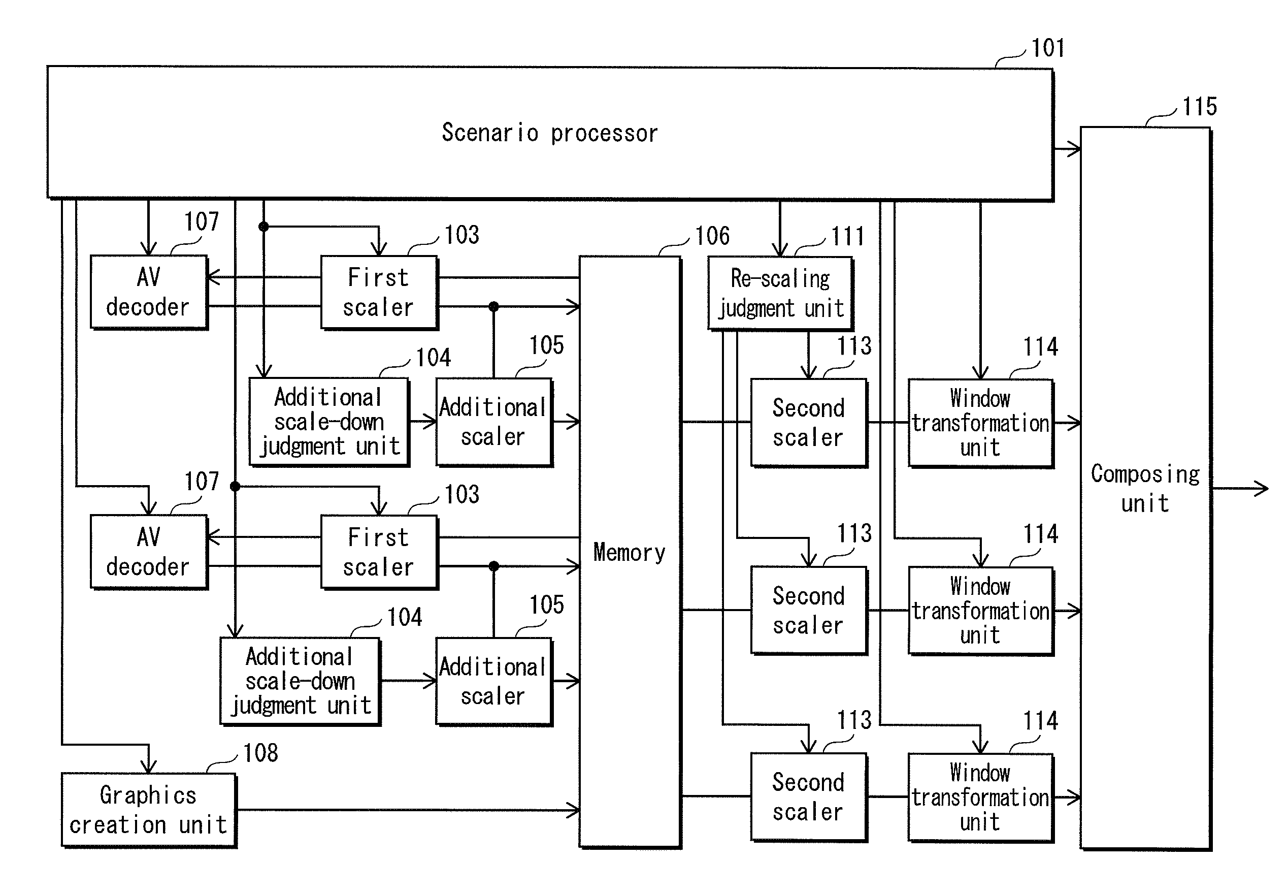
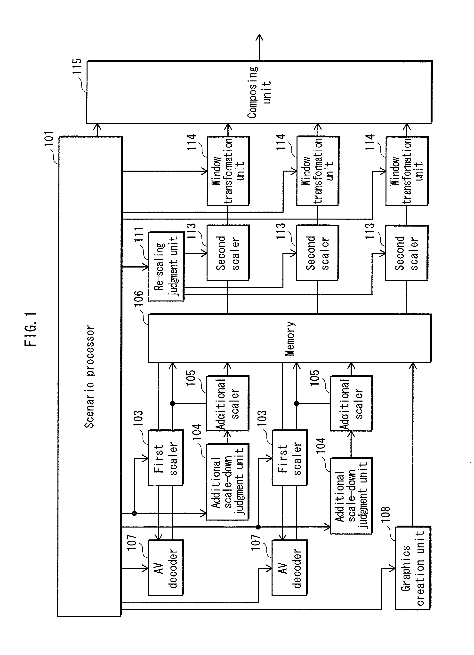
[0057]FIG. 1 shows the hardware configuration of a rendering device relating to a first embodiment of the present invention. The rendering device itself may be used directly by a user in that form or be incorporated into various electronic devices. A representative example of the rendering device is a television receiver. Alternatively the rendering device could be a general purpose computer such as a Personal Computer (PC), an AV device such as an AV playback device, a Personal Digital Assistant (PDA), a tablet, or a communication terminal such as a cellular phone.

[0058]The rendering device includes a scenario processor 101, a AV decoder 107, a graphics creation unit 108, a first scaler 103, an additional scale-down judgment unit 104, an additional scaler 105, a memory 106, a re-scaling judgment unit 111, a second scaler 113, a window transformation unit 114 and a composing unit 115. The present embodiment is explained based on a multi-window display system in which the data of two...

second embodiment

[0099]FIG. 10 shows the hardware configuration of a rendering device relating to a second embodiment of the present invention.

[0100]Compared to the configuration of the rendering device relating to the first embodiment shown in FIG. 1, the rendering device relating to the second embodiment additionally comprises a control unit 110, a resolution control unit 102 and a plurality of feature detection units 112. Furthermore, in the second embodiment a multi-window display with two videos arranged within a screen is realized by scaling-down two videos so that an image selected by a user is displayed large at a size equivalent to ½ the screen size, and a non-selected image is displayed at thumbnail size. In the rendering device relating to the first embodiment the scaled-down picture created by each of the additional scalers 105 is a mipmap, however in the rendering device relating to the second embodiment each of the additional scalers 105 creates a thumbnail size scaled-down picture.

[01...

third embodiment

[0123]FIG. 14 shows the hardware configuration of a television relating to a third embodiment of the present invention.

[0124]The television relating to the third embodiment has the same configuration as the rendering device relating to the second embodiment shown in FIG. 10, but also additionally includes a plurality of tuners 301 and a display 302.

[0125]Each of the tuners 301 selects an indicated channel from received television broadcast waves and acquires encoded data of a video for a screen size of 1920 pixels vertically and 1080 pixels horizontally. The encoded data of the videos acquired by the tuners 301 is output to the AV decoders 107.

[0126]The display 302 is a liquid crystal display of size 1920 pixels vertically and 1080 pixels horizontally, configured to display a multi-window image composed by the composing unit 115.

[0127]In the configuration explained for the present embodiment, by scaling-down each of the pictures to become an image object before storage in the memory...


PUM


Abstract

A rendering device provides improved rendering responsiveness in multi-window display for rendering scenarios in which display sizes of images vary over time, while also reducing required memory bandwidth. The device comprises: a scenario processor 101 for interpreting a rendering scenario and calculating for each frame period a scale-down ratio for each of a plurality of pictures; a plurality of decoders 107 for decoding encoded data of a plurality of videos; a plurality of first scalers for scaling-down the decoded pictures using the scale-down ratios calculated by the scenario processor 101; a memory 106 for storing the scaled-down pictures; a plurality of second scalers 113 for reading the scaled-down pictures from the memory and re-scaling the scaled-down pictures to match the scale-down ratios calculated by the scenario processor for a current frame period; and, a composing unit 115 for composing the re-scaled pictures.

Description

TECHNICAL FIELD[0001]The present invention relates to a rendering device for rendering image objects such as television videos within a screen, and in particular to a multi-window display art in which multiple image objects are rendered within a screen.BACKGROUND ART [0002]Multi-window display art is used to display various contents simultaneously in devices such as televisions, recorders, tablets and smartphones. Multi-window display is used for example to arrange and display the videos of multiple television broadcast channels within a single screen, or to display a television video with graphics used for interactive operation by a user in a data broadcast composed thereon.[0003]Multi-window display may be realized for example by a method for rendering a virtual space video, wherein a plurality of image objects are pasted onto a plurality of surfaces of a virtual space object in accordance with a rendering scenario written for example using OpenGL.[0004]Image objects displayed on ...

Claims


Application Information

Patent Timeline
Patent Type & Authority Applications(United States)
IPC IPC(8): H04N7/01
CPCG09G5/14H04N21/440263G09G5/395H04N7/0117H04N21/4314H04N5/44504H04N21/42653G06T3/4092G09G5/026G09G5/373G09G5/391G09G2340/0442G09G2340/10G09G2354/00G09G5/393
Inventor NISHIDA, HIDESHI
Owner PANASONIC INTELLECTUAL PROPERTY MANAGEMENT CO LTD
Why Eureka
Try Eureka