Capacitor and manufacturing method thereof

a technology of capacitors and manufacturing methods, applied in the field of capacitors, can solve problems such as the disadvantage of non-linear outpu

Active Publication Date: 2013-06-20
IND TECH RES INST
View PDF5 Cites 17 Cited by
  • Summary
  • Abstract
  • Description
  • Claims
  • Application Information

AI Technical Summary

Problems solved by technology

In recent years, the rapid development of economy and the increasing nuclear risk result in urgent need to resolve the issue of energy shortage.
Even though th

Method used


Image

  • Capacitor and manufacturing method thereof
  • Capacitor and manufacturing method thereof
  • Capacitor and manufacturing method thereof

Examples


example 1

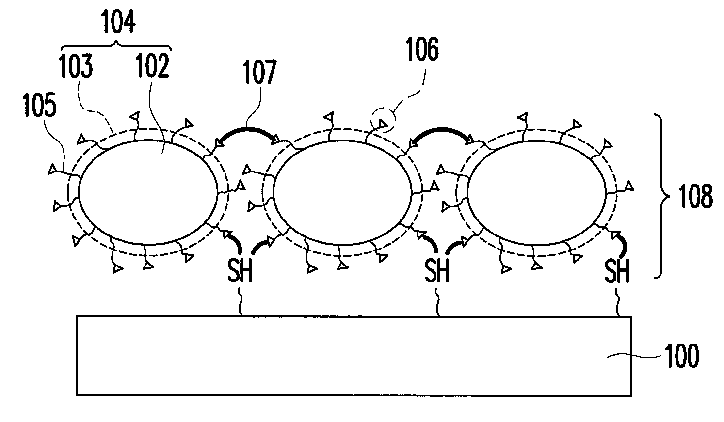
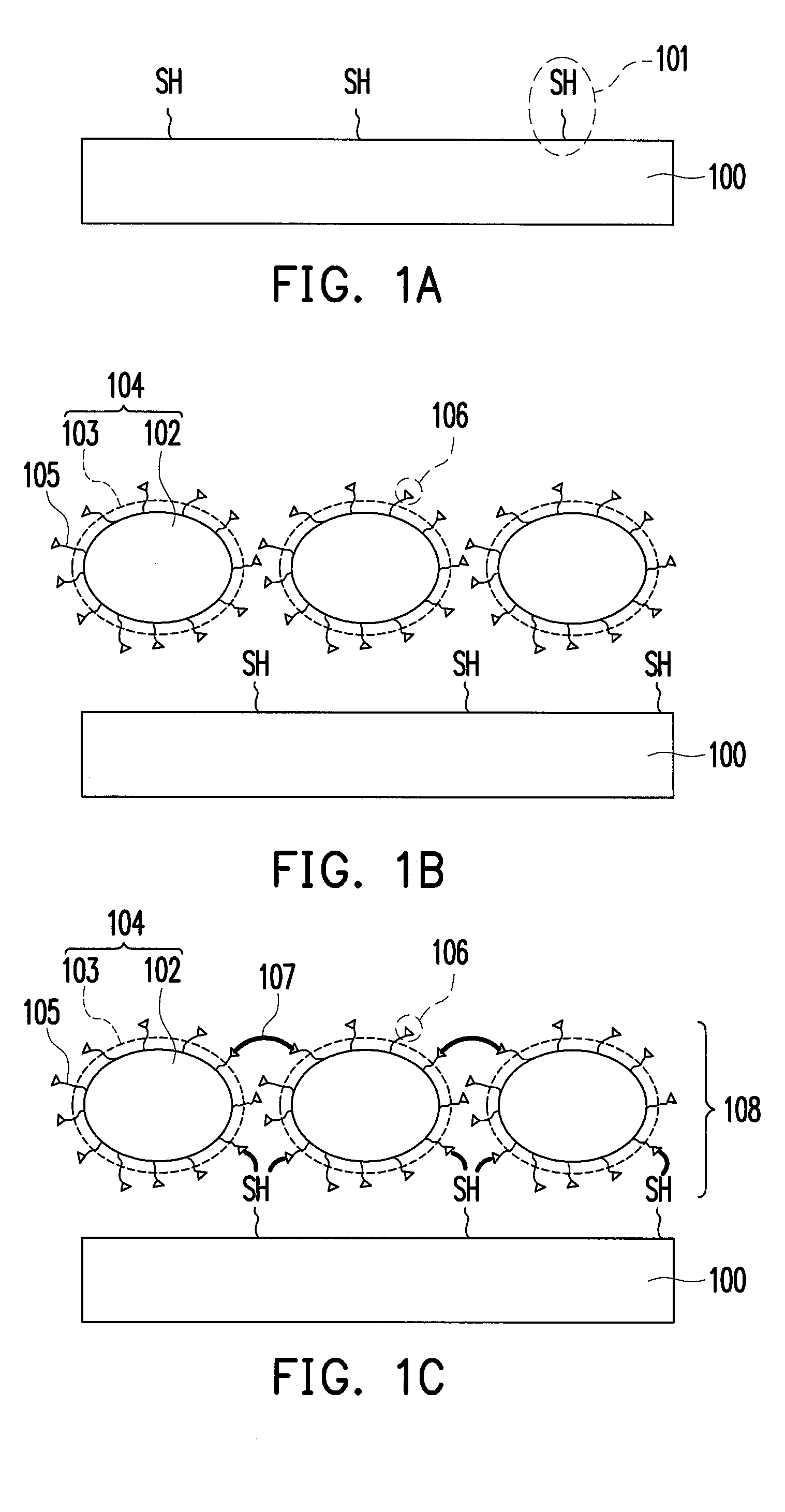
(1) Formation of Electrodes Having Active Carbon Layers and Protection Layers

[0036]Electrode Surface Treatment

[0037]Aluminum foil was dipped into a buffered oxide etch solution (brand name: buffered oxide etch 6:1, purchased from J. T. Baker) for about 0.5 minute to about 10 minutes to remove the metal oxide layer on the surface of the aluminum foil, and the aluminum foil was then moved into water, cleaned, and dried. After that, the aluminum foil was dipped into 3-mercaptopropionic acid for about 0.5 minute to about 10 minutes, taken out and cleaned by tetrahydrofuran, and dried.

[0038]Preparation of Modified Carbon Particles

[0039]1,000 mesh of graphite powder was weighed and added to a beaker. 100 ml of dimethylsulfoxide and 100 ml of monomer solution of glycidyl methacrylate (GMA) were mixed and added to the beaker, and 10 g of benzoyl peroxide (BPO) was gradually added thereto. A polymerization reaction of the monomer solution with the added BPO was carried out at 80° C. under ul...

example 2

[0045]A capacitor was formed by applying the same method described in the Example 1, whereas the aluminum foil was replaced by a stainless steel board serving as the electrodes. The capacitor of Example 2 was then obtained.

example 3

[0046]In the Example 3, a surface modification process was performed on 1,000 mesh of graphite powder. With carbon SP2 structure on the surface of the graphite powder, PGMA was directly grafted onto the graphite powder through radical polymerization. 10 g of graphite powder were dispersed in 100 ml of monomer solution of glycidyl methacrylate (GMA) under ultrasonic to completely disperse the graphite powder, and 10 g of benzoyl peroxide (BPO) as a radial initiator were gradually and constantly added thereto. A polymerization reaction of the monomer solution with the added BPO was carried out at 80° C. under ultrasonic, such that a portion of the polymer radicals were directly grafted onto the surface of the graphite powder. Thereafter, the graphite powder grafted with polymer (or called PGMA grafted graphite powder) in the solution were isolated by high-speed centrifugation and free polymer was removed.

[0047]10 g of the PGMA grafted graphite powder were dispersed in 100 ml of dimeth...


PUM

PropertyMeasurementUnit
Adhesion strengthaaaaaaaaaa
Molecular weightaaaaaaaaaa

Abstract

A capacitor and a manufacturing method thereof are provided. Two electrodes are disposed opposite to each other. Two electrode protection layers are respectively disposed on inner sides of the electrodes and include carbon particles each covered and bonded with a polymer shell. Active carbon layers are disposed on opposite inner sides of the electrode protection layers. The separator is disposed between the active carbon layers. The electrolyte fills between the electrode protection layers. The polymer shells of each electrode protection layer are bonded to the surface of the corresponding electrode by first and second functional groups. The first functional groups include thiol groups. The second functional groups include epoxy groups or carboxylic groups. The electrode protection layers serve as adhesion layers between the active carbon layers and the electrodes, and protect the electrodes from being corroded by the acid electrolyte solution.

Description

CROSS-REFERENCE TO RELATED APPLICATION[0001]This application claims the priority benefits of Taiwan application serial no. 100146543, filed on Dec. 15, 2011 and Taiwan application serial no. 101120686, filed on Jun. 8, 2012. The entirety of each of the above-mentioned patent applications is hereby incorporated by reference herein and made a part of this specification.BACKGROUND[0002]1. Technical Field[0003]The technical field relates to a capacitor and a manufacturing method thereof.[0004]2. Background[0005]In recent years, the rapid development of economy and the increasing nuclear risk result in urgent need to resolve the issue of energy shortage. Besides, as the consciousness of environmental protection gradually rises, people are eager for clean renewable energy, thus advancing the development of solar energy, wind power generation, and electricity for powering electric vehicles. Even though the clean natural renewable energy is inexhaustible, the natural energy input to a devic...

Claims


Application Information

Patent Timeline
IPC IPC(8): H01G9/00H01G9/042
CPCH01G11/24H01G11/28Y10T29/417H01G11/86Y02E60/13H01G11/32
Inventor TSAI, HSIEH-HOHSIN, YU-LINLIN, YU-MINGCHEN, LI-KEYWANG, MEI-HUACHANG, CHIH-KUANG
Owner IND TECH RES INST
Why Eureka
Try Eureka