Forcible entry device

Inactive Publication Date: 2013-06-27
MELTON JOSEPH L
View PDF2 Cites 3 Cited by
  • Summary
  • Abstract
  • Description
  • Claims
  • Application Information

AI Technical Summary

Benefits of technology

The invention is a forcible entry device or door breaching device that is designed to be attached to the muzzle of a weapon such as a rifle or shotgun. The device includes an elongated tube with a chamber formed inside it, a piston and a ram plate that are all secured within the tube. The device also includes guide rods and a stand-off member for safely and conveniently using it. The device can be used to breach doors by discharging a blank cartridge or shell from the weapon. The device is safe and easy to use.

Problems solved by technology

Moreover, this Summary is not intended for use as an aid in determining the scope of the claimed subject matter.

Method used


Image

  • Forcible entry device
  • Forcible entry device
  • Forcible entry device

Examples


Embodiment Construction

[0021]Embodiments are described more fully below with reference to the accompanying figures, which form a part hereof and show, by way of illustration, specific exemplary embodiments. These embodiments are disclosed in sufficient detail to enable those skilled in the art to practice the invention. However, embodiments may be implemented in many different forms and should not be construed as being limited to the embodiments set forth herein. The following detailed description is, therefore, not to be taken in a limiting sense in that the scope of the present invention is defined only by the appended claims.

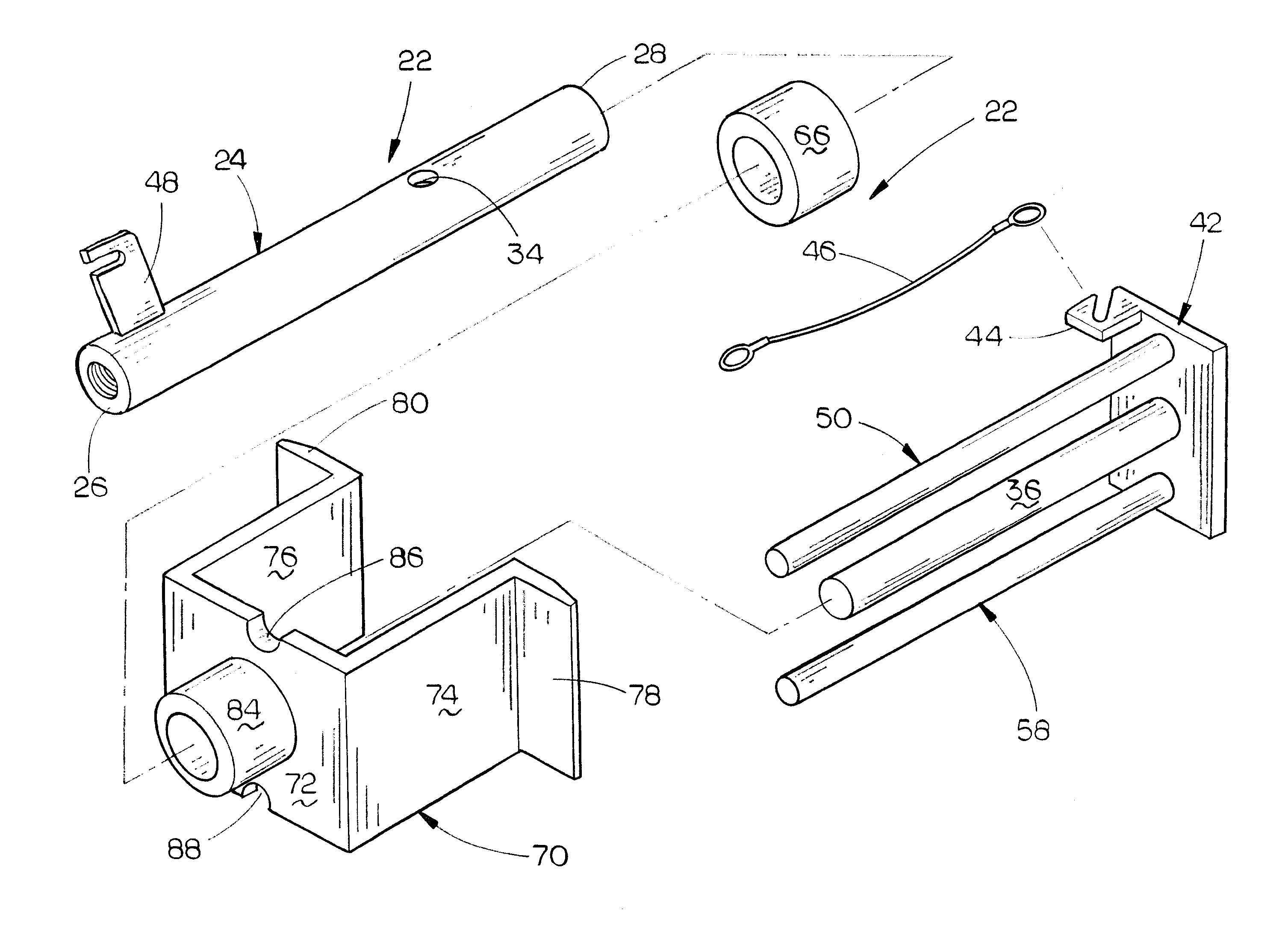
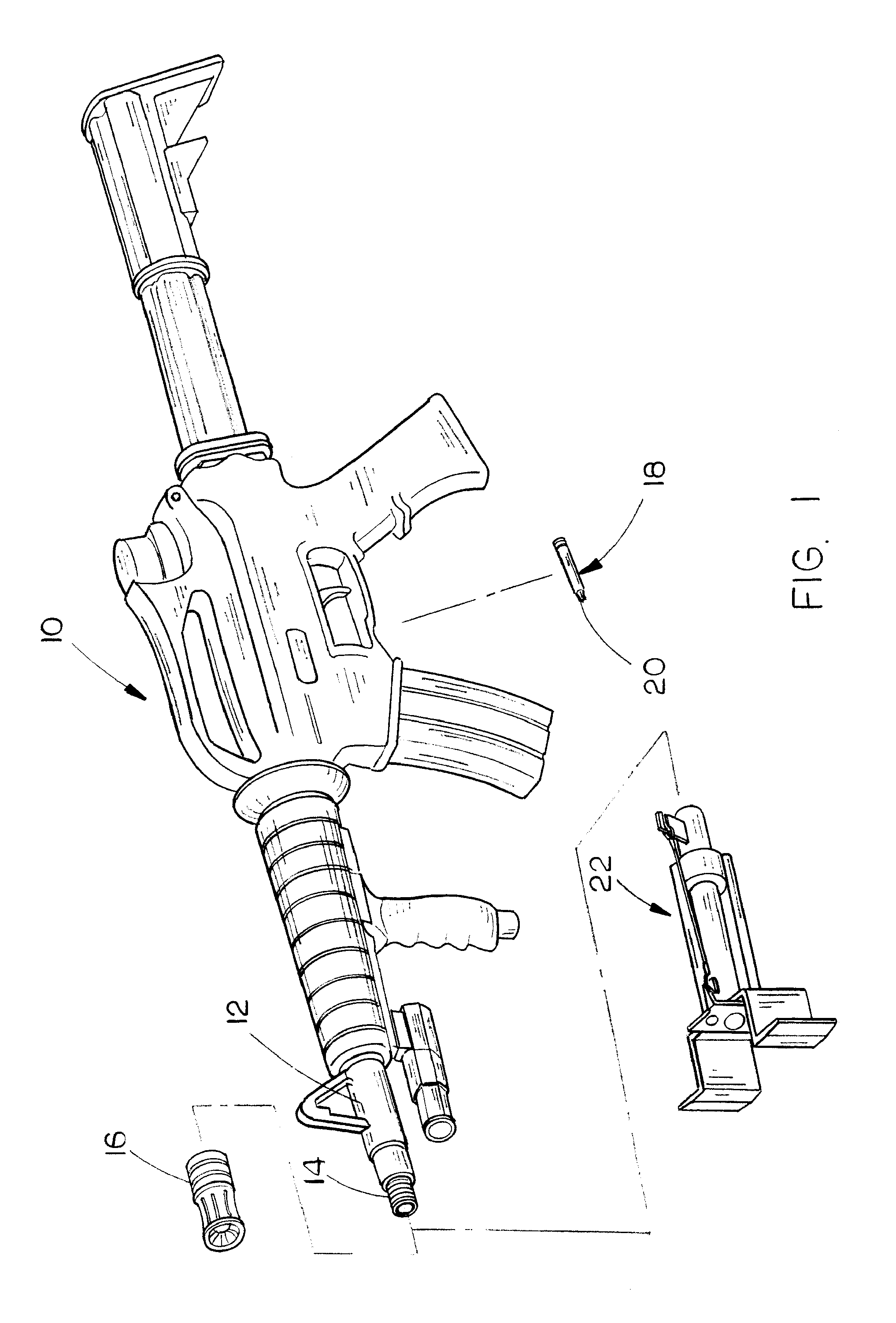
[0022]The numeral 10 refers to a weapon such as a rifle which may be an AR-15, AK-47, etc. A shotgun could be used in place of the rifle 10 if so desired. Rifle 10 includes a barrel 12 having an externally threaded muzzle 14 which is adapted to have a device 16 secured thereto. Device 16 is sometimes termed a muzzle brake, flash arrestor, flash hider or compensator. The numeral 18 ...


PUM


Abstract

A forcible entry device or door breaching device for attachment to the muzzle of a rifle or shotgun. The device includes a ram which is driven into the door by the explosive gases discharged from a blank cartridge or shell.

Description

BACKGROUND OF THE INVENTION[0001]1. Field of the Invention[0002]This invention relates to a forcible entry device or a door breaching device which may be selectively attached to the muzzle of a weapon such as a rifle or shotgun.[0003]2. Description of the Related Art[0004]Many types of forcible entry devices or door breaching devices have been previously provided to enable law enforcement personnel or military personnel to quickly gain access into a building, dwelling, etc. having a doorway which is closed by a door. For example, U.S. Pat. No. 6,408,765 discloses a rifle grenade for blasting an object at a short range. The rifle grenade of the '765 Patent is not designed to be placed directly against the door. Further, the device of the 765 Patent requires a special grenade. U.S. Pat. No. 6,318,228 discloses a portable hand-held forcible entry device which drives a striker having a tool bit attached thereto. The '228 Patent requires that the barrel of the firing weapon be removed.[0...

Claims


Application Information

Patent Timeline
IPC IPC(8): F41C27/00
CPCF41A21/32F41C27/00
Inventor MELTON, JOSEPH L.
Owner MELTON JOSEPH L
Why Eureka
Try Eureka