Method and system for controlling a power source at a rock drilling apparatus and rock drilling apparatus

a technology for rock drilling and rock drilling, which is applied in the direction of automatic control of drilling, drilling accessories, earthwork drilling and mining, etc., can solve the problems of excessive fuel consumption, unoptimized power source many times, and undesired generation of heat and nois

Active Publication Date: 2013-06-27
EPIROC ROCK DRILLS AB
View PDF3 Cites 7 Cited by
  • Summary
  • Abstract
  • Description
  • Claims
  • Application Information

AI Technical Summary

Benefits of technology

[0030]This has the advantage that the consumer can require a flow that is completely independent from the rotation speed at which the hydraulic pump must be driven in order to deliver a requested flow. This also means that the consumer can request a flow, where said request is completely independent from the type of hydraulic pump that is powering the consumer. Consequently, as seen from the consumer, it does not matter if it is a small or large hydraulic pump that powers the consumer, the only point of interest is that a desired flow is obtained. This also means that the hydraulic pump can be replaced from one type to another without the manner in which a requested hydraulic flow is determined must be changed, since the responsibility for obtaining a “correct” flow is completely the responsibility of the load.
[0031]Consequently, components can be replaced in a simple manner without necessarily affecting the portions of the control system that relate to units controlling / being controlled by a replaced component.

Problems solved by technology

However, in many situations of operation the full capacity of the loads and / or consumers is not utilized, which also means that the power source many times is driven at a speed that is not optimal.
This also means that rock drilling apparatuses often consume more power than necessary during a drilling process, which results in excessive fuel consumption and also undesired generation of heat and noise.

Method used


Image

  • Method and system for controlling a power source at a rock drilling apparatus and rock drilling apparatus
  • Method and system for controlling a power source at a rock drilling apparatus and rock drilling apparatus
  • Method and system for controlling a power source at a rock drilling apparatus and rock drilling apparatus

Examples


Embodiment Construction

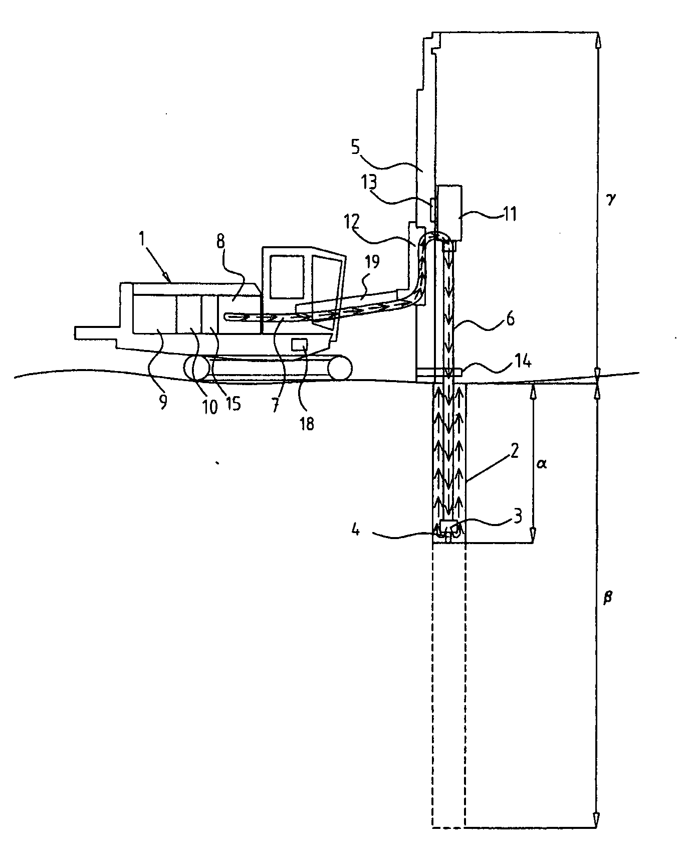
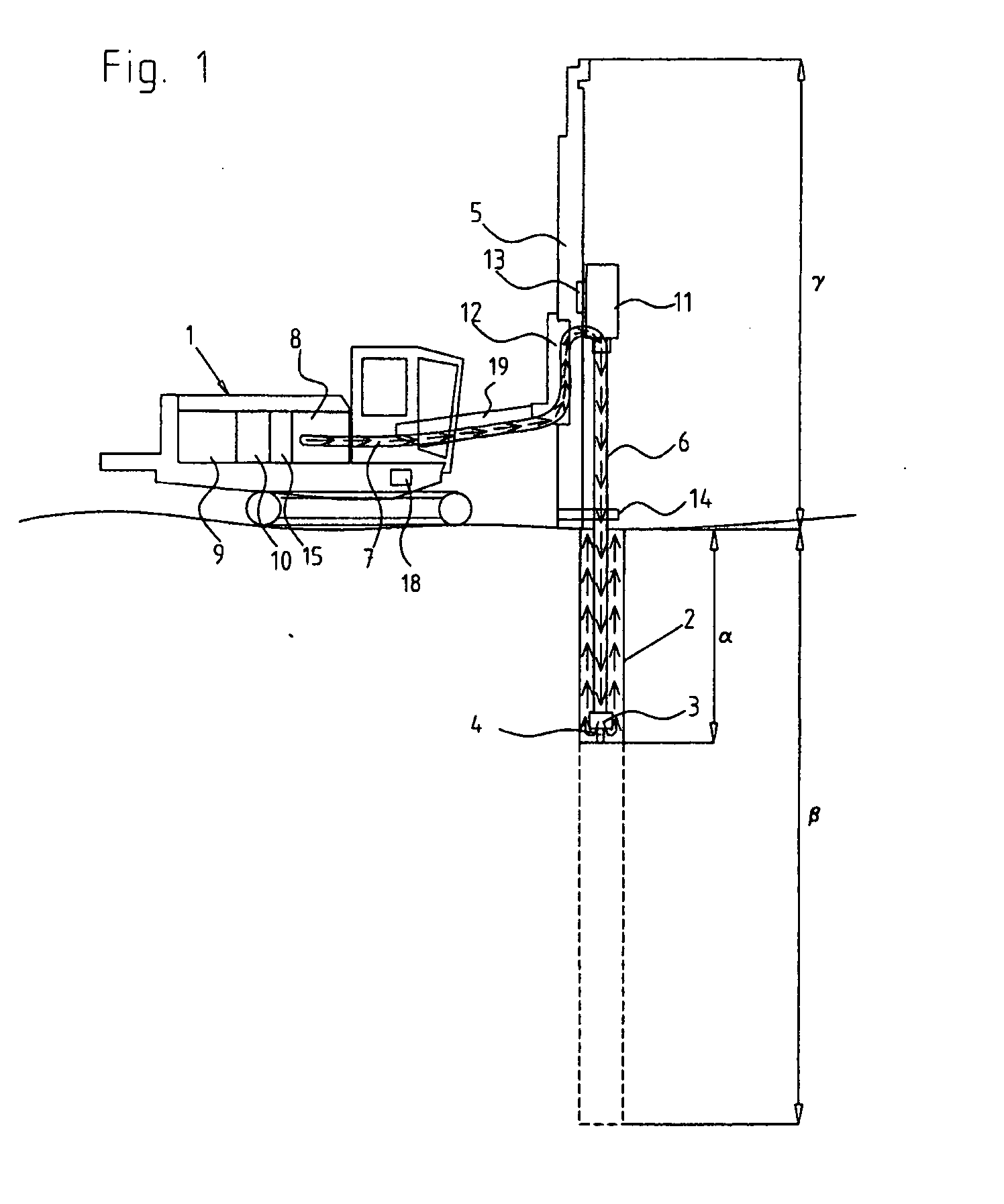
[0037]FIG. 1 shows a rock drilling apparatus according to a first exemplary embodiment of the present invention for which an inventive control of a compressor will be described.

[0038]The rock drilling apparatus shown in FIG. 1 includes a drilling rig 1, in this example a surface drilling rig, which carries a drilling machine in the form of a top hammer drilling machine 11.

[0039]The drilling rig 1 is shown in use, drilling a hole 2 in rock, which starts at the surface and where the drilling at present is at a depth α. The hole is intended to result in a hole having the depth β, which, depending on area of use, can vary to large extent from hole to hole and / or from area of use to area of use. The finished hole is indicated by dashed lines. (The shown relationship between drilling rig height and hole depth is not intended to be proportional in any way. The total height Υ of the drilling rig can, for example be 10 meters, while the hole depth β can be both less than and considerably lar...


PUM


Abstract

The present invention relates to a method for controlling a power source (9) at a rock drilling apparatus, said power source (9) being arranged to drive at least a first load (8,10,15) at the rock drilling apparatus, wherein said first load (8,10,15), in operation, provides power to a first consumer (11,21), and where the power that can be delivered by- said first load (8,10,15) depends on the rotation speed of the power source. The method includes, by means of a representation of said first consumer (11,21), determining a power demand of said first consumer (11,21), and based on said determined power demand, determine a rotation speed demand of said first load (8,10,15). The rotation speed of said power source is then controlled based at least on said determined rotation speed demand of said first load (8, 10, 15 ). The invention also relates to a system and a rock drilling apparatus.

Description

FIELD OF THE INVENTION[0001]The present invention relates to methods and systems for controlling power sources, and in particular to a method for controlling a power source during rock drilling. The invention also relates to a system and a rock drilling apparatus.BACKGROUND OF THE INVENTION[0002]Rock drilling apparatuses may be used in a number of areas of application. For example, rock drilling apparatuses may be used in tunnelling, underground mining, rock reinforcement, raise boring, and for drilling of blast holes, grout holes and holes for installing rock bolts, etc.[0003]A drill tool such as, for example, a drill bit is often used during drilling, the drill bit being connected to a drilling machine, in general by means of a drill string. The drilling can be accomplished in various ways, e.g. as rotational drilling where the drill tool is pushed towards the rock at high pressure and then crushes the rock by means of rotation force and applied pressure.[0004]Percussive drilling ...

Claims


Application Information

Patent Timeline
Patent Type & Authority Applications(United States)
IPC IPC(8): E21B44/00
CPCE21B44/00E21B44/06
Inventor NYDAHL, ANDERSALDEN, ERIK
Owner EPIROC ROCK DRILLS AB
Why Eureka
Try Eureka