Power receiving device and wireless power supply system

wireless technology, applied in the direction of safety/protection circuits, inductances, transportation and packaging, etc., can solve the problems of low power transmission efficiency of total power transmitted, power consumption, and low power transmission efficiency of power supplied to a power receiving device while charging, so as to improve power transmission efficiency, reduce q-value, and high power transmission efficiency

Active Publication Date: 2013-06-27
SEMICON ENERGY LAB CO LTD
View PDF5 Cites 35 Cited by
  • Summary
  • Abstract
  • Description
  • Claims
  • Application Information

AI Technical Summary

Benefits of technology

[0017]In the power receiving device according to one embodiment of the present invention, the pair of power supply points of the antenna element of the power receiving antenna is short-circuited. With the above structure, supply of power to a circuit element, a wiring, and the like that are connected to the power receiving antenna is stopped; therefore, the resonant antenna of the power receiving device does not substantially receive power from the resonant antenna of the power supply device. Therefore, in the power receiving device according to one embodiment of the present invention, supply of power from the power supply device can be stopped without a short-circuit between the pair of power supply points of the antenna element of the resonant antenna. Further, in a wireless power supply system

Problems solved by technology

However, in the case of a plurality of power receiving devices, even when the resonance frequency of the power supply device is equal to that of the power receiving device, power transmission efficiency of the total power transmitted from the power supply device to the plurality of power receiving devices is lower than in the case where one power supply device is paired with one power receiving device because resonant antennas of the plurality of power receiving devices interfere with each other.
Further, in a power receiving device in which charging is completed and supply of power is unnecessary, a circuit element, a wiring, and the like that are connected to a power receiving antenna are charged and discharged, which causes power

Method used


Image

  • Power receiving device and wireless power supply system
  • Power receiving device and wireless power supply system
  • Power receiving device and wireless power supply system

Examples


embodiment 1

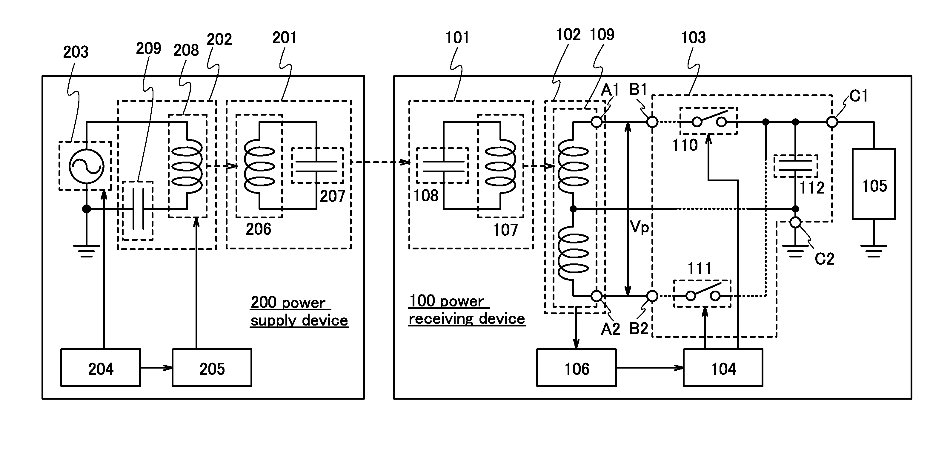
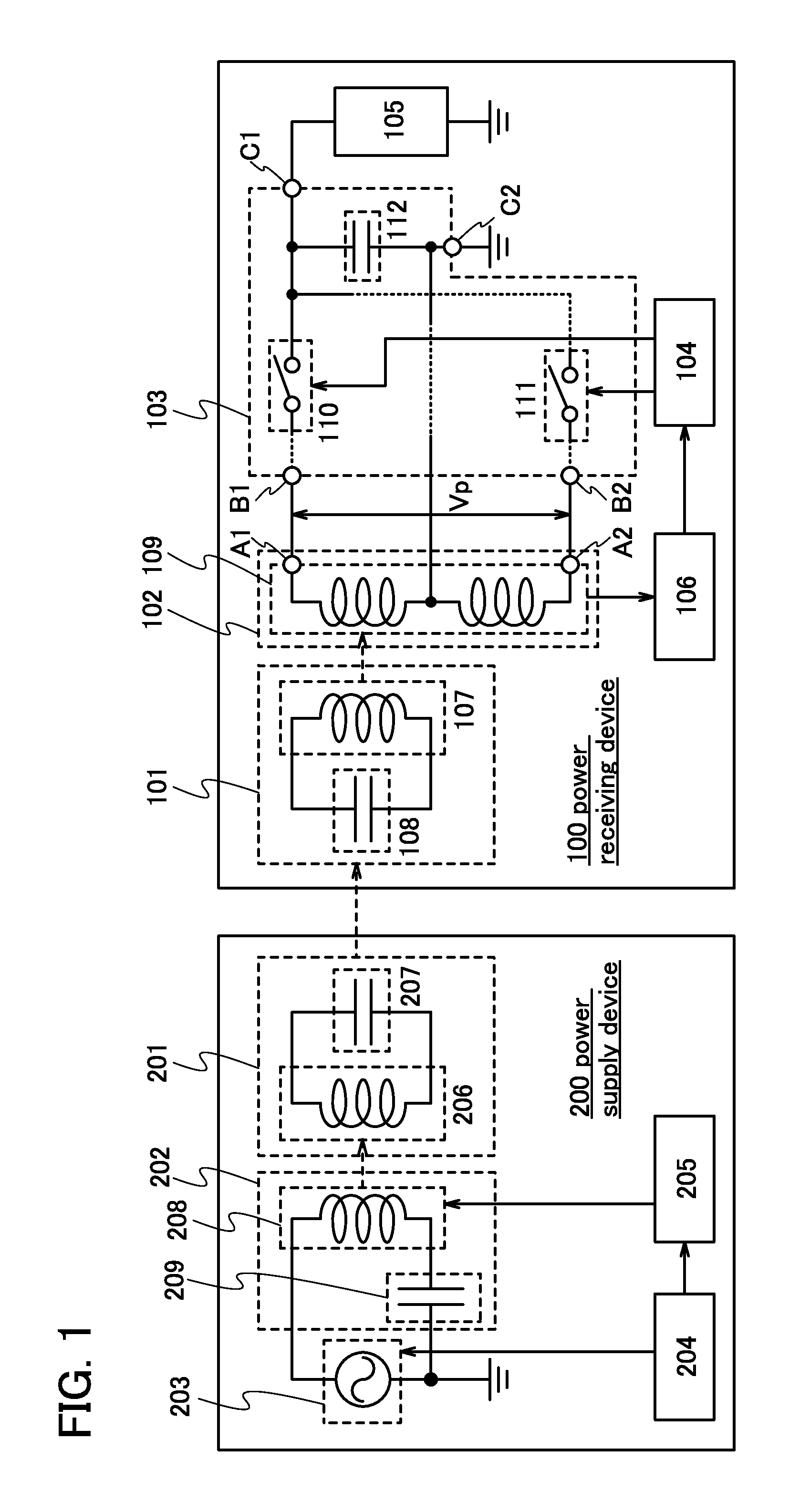
[0031]FIG. 1 illustrates an example of a wireless power supply system according to one embodiment of the present invention. The wireless power supply system in FIG. 1 includes a power receiving device 100 and a power supply device 200.

[0032]The power receiving device 100 includes a resonant antenna 101, a power receiving antenna 102, a rectifier circuit 103, a control circuit 104, a load 105, and a receiving circuit 106. Further, the power supply device 200 includes a resonant antenna 201, an antenna 202, an AC power source 203, a control circuit 204, and a transmitting circuit 205.

[0033]First, a specific structure of the power supply device 200 is described.

[0034]The resonant antenna 201 includes an antenna element 206 that is an inductor and capacitance in the antenna element 206. Further, in order to adjust the resonant frequency of the resonant antenna 201, a capacitor may be connected to the antenna element 206 in addition to the capacitance in the antenna element 206. In FIG. ...

embodiment 2

[0076]In this embodiment, the structure of the power receiving device 100 which uses a power storage device as the load 105 is described.

[0077]FIG. 5 illustrates the structure of the power receiving device 100 according to one embodiment of the present invention. The power receiving device 100 in FIG. 5 is different from the power receiving devices 100 in FIG. 1 and FIG. 2 in the structure of the load 105. In FIG. 5, the load 105 includes a power storage device 114 and a charge control circuit 115. Note that the load 105 may include a load in addition to the power storage device 114 and the charge control circuit 115.

[0078]Current is supplied to the power storage device 114 using voltage transmitted from the rectifier circuit 103, whereby charge is stored in the power storage device 114; therefore, power is stored in the power storage device 114. The power storage device 114 includes at least a pair of input terminals; charge is supplied from one input terminal and a reference poten...

embodiment 3

[0087]The present inventor measured loss of power transfer in wireless power supply from a power supply device to a power receiving device. In this embodiment, the results are described.

[0088]The loss of power transfer was measured using different three conditions. Under a first condition, as shown in FIG. 6A, a power supply device 301 and a power receiving device 303 were used. In the power receiving device 303, it is estimated that the first operation was performed in a rectifier circuit. Under the first condition, the power receiving device 303 was arranged within a region where a radio wave outputted from the power supply device 301 could be received.

[0089]Under a second condition, as shown in FIG. 6B, the power supply device 301, the power receiving device 303, and a power receiving device 304 were used. In the power receiving devices 303 and 304, it is estimated that the first operation was performed in the rectifier circuit. Under the second condition, the power receiving dev...


PUM


Abstract

Provided is a power receiving device in which supply of power from a power supply device can be stopped while a reduction in Q-value is suppressed. The power receiving device includes a first antenna which forms resonant coupling with an antenna of the power supply device; a second antenna which forms electromagnetic induction coupling with the first antenna; a rectifier circuit including a plurality of switches and performing a first operation or a second operation depending on whether the plurality of switches is ON or OFF, the first operation being an operation in which voltage applied from the second antenna is rectified to be outputted, and the second operation being an operation in which a pair of power supply points is short-circuited; a load to which the voltage is applied; and a control circuit which generates a signal for selecting ON or OFF of the plurality of switches.

Description

BACKGROUND OF THE INVENTION[0001]1. Field of the Invention[0002]The present invention relates to a power receiving device that wirelessly receives power, a wireless power supply system including the power receiving device, and a wireless power supply method.[0003]2. Description of the Related Art[0004]A wireless power supply technique for wirelessly supplying power from a power supply device to a power receiving device by electromagnetic induction has been developed and come into practical use. In recent years, a wireless power supply technique for supplying power by electromagnetic resonance (electromagnetic resonant coupling) that enables long-distance power transmission as compared to a wireless power supply technique for supplying power by electromagnetic induction has attracted attention. Unlike by electromagnetic induction, by electromagnetic resonance, high power transmission efficiency can be maintained even when the transmission distance is several meters, and power loss du...

Claims


Application Information

Patent Timeline
IPC IPC(8): H02J7/02H01F38/14
CPCH02J7/025H02J5/005H01F38/14H02J7/0068H02J2207/50H02J50/005H02J7/00302H02J50/80H02J50/90H02J50/12H02J7/0049H02J50/40H02M3/06F02P3/02H02M1/12
Inventor KAMATA, KOICHIRO
Owner SEMICON ENERGY LAB CO LTD
Why Eureka
Try Eureka