
Device and method for denoising ocean bottom data

a technology of ocean bottom data and devices, applied in measurement devices, scientific instruments, instruments, etc., can solve problems such as inability to remove notches or gaps in frequency content, and affect wave-field separation results,

Active Publication Date: 2013-06-27
CGGVERITAS SERVICES
View PDF16 Cites 6 Cited by
  • Summary
  • Abstract
  • Description
  • Claims
  • Application Information

AI Technical Summary

Benefits of technology

The patent text describes a method for improving the quality of marine seismic data recorded with two sensors. The method involves using models of the seismic data in a transform domain to separate out the noise from the data. The noise is then reversed transformed back to the time-space domain and subtracted from the data to denoise it. This results in a cleaner and more accurate representation of the marine seismic data. The patent also describes a computing device and computer-readable medium for implementing this method. The technical effect of the patent is to improve the quality and accuracy of marine seismic data.

Problems solved by technology

In essence, interference between primary and ghost arrivals causes notches or gaps in the frequency content, and these notches cannot be removed without the combined use of advanced acquisition and processing techniques.
However, in OBC and OBN data processing, wave-field separation results are sometimes affected by high levels of noise on the vertical component Z, while the pressure component P is generally of good quality.
While this method is effective at removing noise which is not present in the P-component, it has the disadvantage that the Z is scaled in amplitude to look like P, which is undesirable.
However, the existing methods might not preserve the signal during the processing because it is known that any mathematical transformation used to manipulate the data from one domain to another domain introduces spurious features.
In addition, if sparse transforms are not used, the areas of signal and coherent noise may overlap, thus, making it impossible to isolate the noise.

Method used


Image

  • Device and method for denoising ocean bottom data
  • Device and method for denoising ocean bottom data
  • Device and method for denoising ocean bottom data

Examples


Embodiment Construction

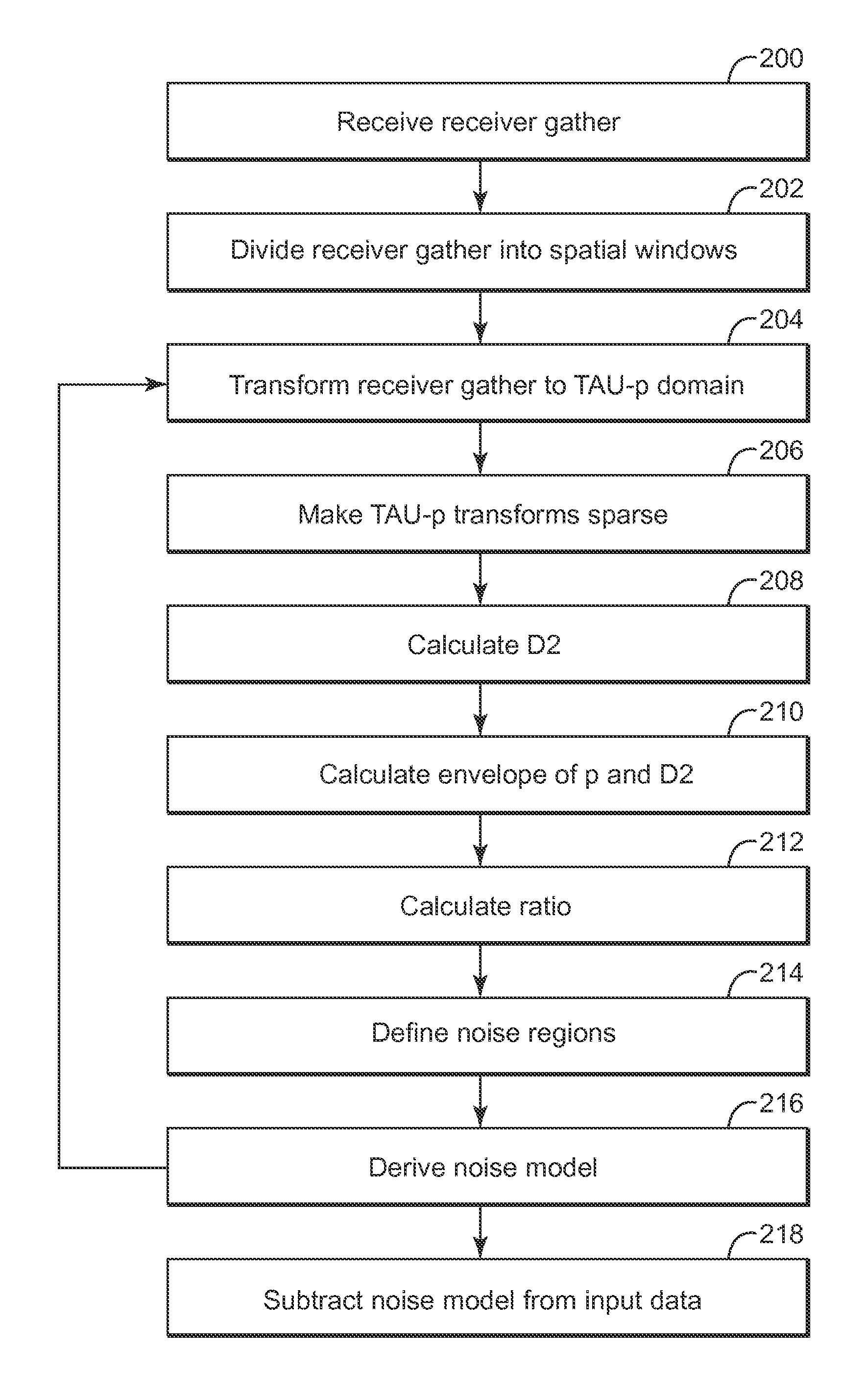
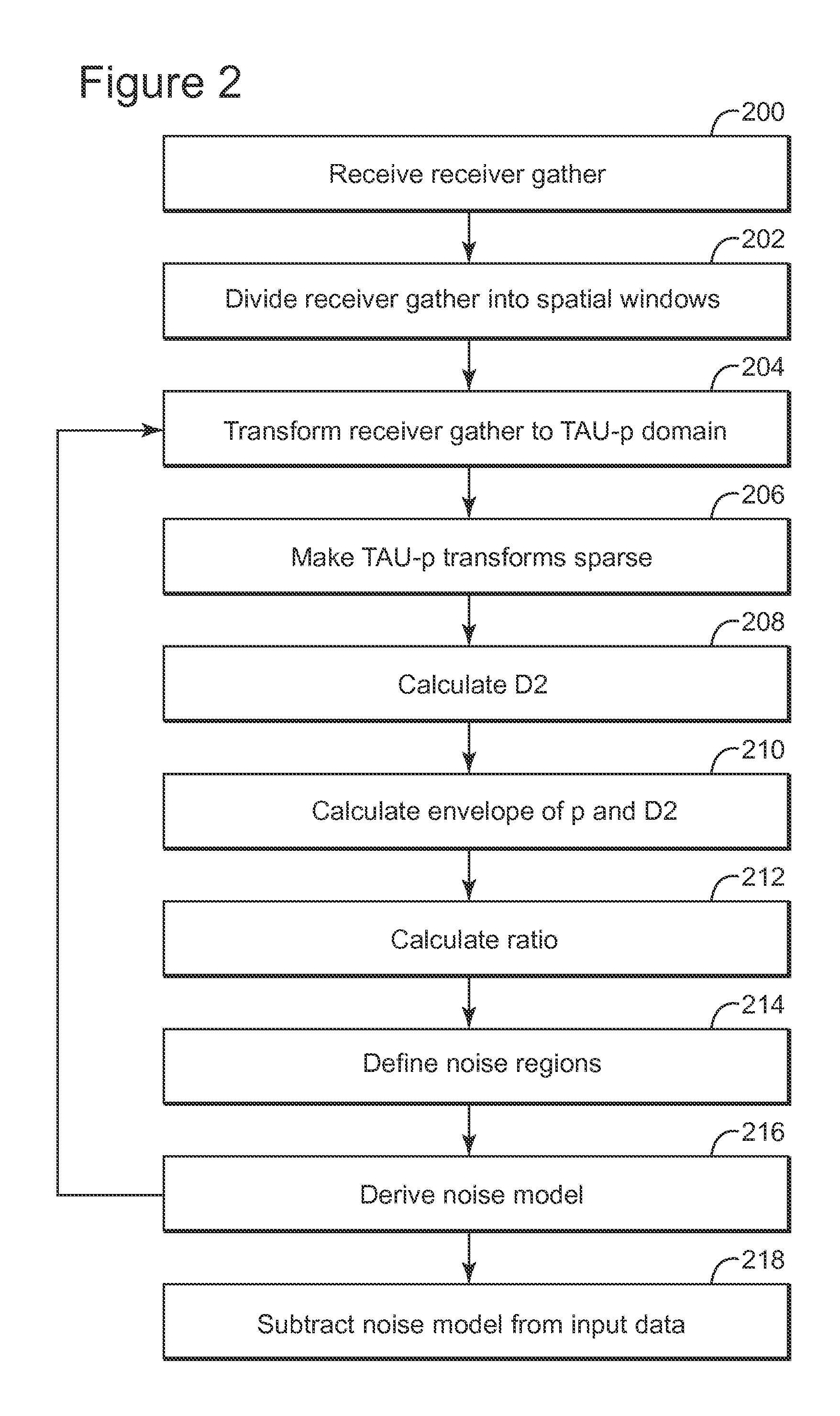
[0025]The following description of the exemplary embodiments refers to the accompanying drawings. The same reference numbers in different drawings identify the same or similar elements. The following detailed description does not limit the invention. Instead, the scope of the invention is defined by the appended claims. The following embodiments are discussed, for simplicity, with regard to seismic data that is processed, in a pre-stack step, with sparse Radon transforms. Further, the following embodiments disclose using the down-going wave and pressure above ocean bottom to determine the noise. However, the embodiments to be discussed next are not limited to the Radon transforms, or to down-going wave and pressure above ocean bottom, but they may be extended or used with other mathematical transforms, with up-going wave and pressure, with both up-going and down-going, either above the ocean bottom or below the ocean bottom.

[0026]Reference throughout the specification to “one embodi...


PUM


Abstract

Computing device, computer instructions and method for denoising marine seismic data recorded with first and second seismic sensors. The method includes receiving first seismic data recorded with the first sensor in a time-space domain; receiving second seismic data recorded with the second sensor in the time-space domain, wherein the first and second seismic data are recorded at the same locations underwater; calculating with a processor models of the first and second seismic data in a transform domain that is different from the time-space domain; performing a wavefield separation using the first and second datasets in the transform domain; determining a noise in the transform domain corresponding to the second seismic data based on the wavefield separation; reverse transforming the noise from the transform domain into the time-space domain; and denoising the second seismic data by subtracting the noise in the time-space domain from the second seismic data.

Description

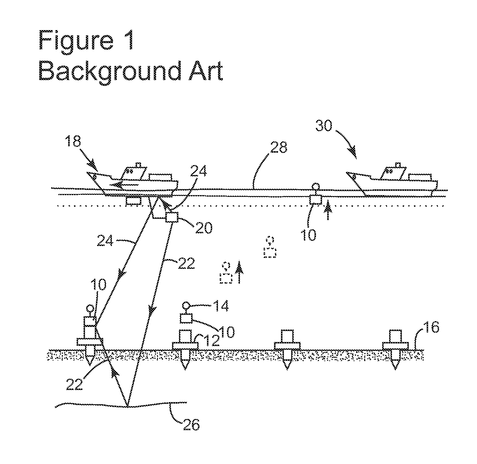
BACKGROUND[0001]1. Technical Field[0002]Embodiments of the subject matter disclosed herein generally relate to methods and systems and, more particularly, to mechanisms and techniques for removing noise from seismic data recorded underwater by a seismic receiver.[0003]2. Discussion of the Background[0004]Marine seismic data acquisition and processing generate an image of a geophysical structure (subsurface) under the seafloor. While this image / profile does not provide a precise location for oil and gas reservoirs, it suggests, to those trained in the field, the presence or absence of oil and / or gas reservoirs. Thus, providing a high resolution image of the subsurface is an ongoing process for the exploration of natural resources, including, among others, oil and / or gas.[0005]A traditional marine system for recording seismic waves is illustrated in FIG. 1, and this system is described in European Patent No. EP 1 217 390, the entire content of which is incorporated herein by reference...

Claims


Application Information

Patent Timeline
Patent Type & Authority Applications(United States)
IPC IPC(8): G01V1/38
CPCG01V2210/32G01V1/36G01V1/38
Inventor POOLE, GORDONGRION, SERGIO
Owner CGGVERITAS SERVICES
Learn More