Apparatus for compensating for distortion of transmitter array in radio communication system and method for controlling the same

a transmitter array and antenna technology, applied in diversity/multi-antenna systems, baseband system details, amplifier modifications to reduce non-linear distortion, etc., can solve the problems of increasing increasing the cost and power, and increasing the hardware complexity. , to achieve the effect of minimizing the external size minimizing the hardware complexity of the transmitter array, and minimizing the power consumption of the transmitter array

Inactive Publication Date: 2013-06-27
SAMSUNG ELECTRONICS CO LTD +1
View PDF3 Cites 18 Cited by
  • Summary
  • Abstract
  • Description
  • Claims
  • Application Information

AI Technical Summary

Benefits of technology

[0012]Further another aspect of exemplary embodiments of the present invention is to provide an apparatus for compensating for distortion of a transmitter array to minimize the external size of the transmitter array in a radio communication system, and a method for controlling the same.
[0013]Yet another aspect of exemplary embodiments of the present invention is to provide an apparatus for compensating for distortion of a transmitter array to minimize the hardware complexity of the transmitter array in a radio communication system, and a method for controlling the same.
[0014]Still another aspect of exemplary embodiments of the present invention is to provide an apparatus for compensating for distortion of a transmitter array to minimize the power consumption of the transmitter array in a radio communication system, and a method for controlling the same.
[0015]Still another aspect of exemplary embodiments of the present invention is to provide an apparatus for compensating for distortion of a transmitter array to minimize the cost of the transmitter array in a radio communication system, and a method for controlling the same.

Problems solved by technology

Thus, implementing a transmitter array with small low-power RF devices is a new technical challenge.
However, in this structure where a DPD is connected to each of power amplifiers included in the transmitter array to perform a pre-distortion operation, one power amplifier needs to use one DPD, causing an increase in the external size of the transmitter array, an increase in the hardware complexity, and an increase in the cost and power.

Method used


Image

  • Apparatus for compensating for distortion of transmitter array in radio communication system and method for controlling the same
  • Apparatus for compensating for distortion of transmitter array in radio communication system and method for controlling the same
  • Apparatus for compensating for distortion of transmitter array in radio communication system and method for controlling the same

Examples


Embodiment Construction

[0023]Preferred embodiments of the present invention will now be described in detail with reference to the accompanying drawings. In the following description, specific details such as detailed configuration and components are merely provided to assist the overall understanding of exemplary embodiments of the present invention. Therefore, it should be apparent to those skilled in the art that various changes and modifications of the embodiments described herein can be made without departing from the scope and spirit of the invention. In addition, descriptions of well-known functions and constructions are omitted for clarity and conciseness.

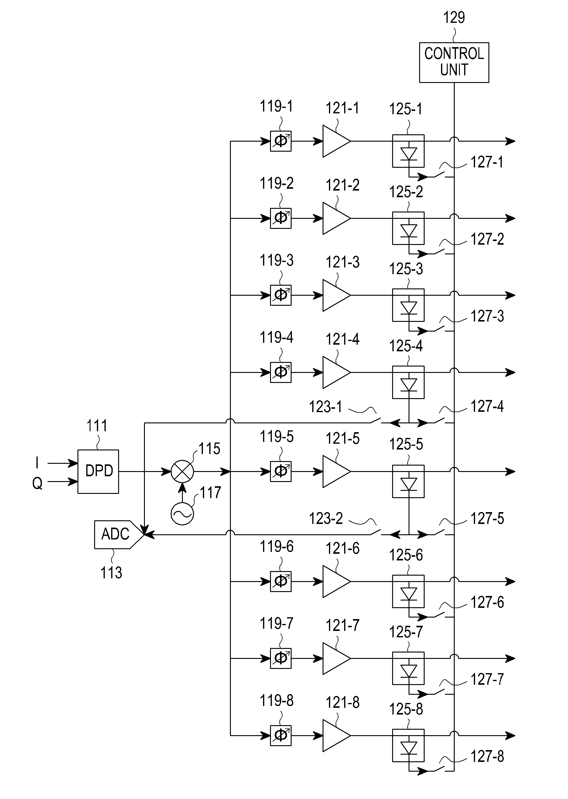
[0024]An aspect of the present invention provides an apparatus for compensating for distortion of a transmitter array in a radio communication system, and a method for controlling the same.

[0025]Another aspect of the present invention provides an apparatus for compensating for distortion of a transmitter array using a minimum number of Digital Pre...


PUM


Abstract

Provided is a method in which a Digital Pre-Distorter (DPD) performs digital pre-distortion on a received In-phase (I) signal, a received Quadrature-phase (Q) signal, a feedback I signal, and a feedback Q signal; a mixer mixes a signal output from the DPD with a frequency signal output from an oscillator; each of n phase shifters phase-shifts a signal output from the mixer according to a preset beamforming pattern; each of n Power Amplifiers (PAs) amplifies a signal output from an associated phase shifter according to a gain, the PAs connected to the associated phase shifter on a one-to-one basis; each of n envelope detectors detects an envelope signal from a signal output from an associated PA, the envelope detector connected to the associated PA on a one-to-one basis; and a control unit determines whether the n PAs operate normally, using the envelope signals output from the n envelope detectors.

Description

PRIORITY[0001]This application claims the benefit under 35 U.S.C. §119(a) of a Korean Patent Application filed in the Korean Intellectual Property Office on Dec. 26, 2011 and assigned Serial No. 10-2011-0141956, the entire disclosure of which is incorporated herein by reference.JOINT RESEARCH AGREEMENT[0002]The presently claimed invention was made by or on behalf of the below listed parties to a joint research agreement. The joint research agreement was in effect on or before the date the claimed invention was made and the claimed invention was made as a result of activities undertaken within the scope of the joint research agreement. The parties to the joint research agreement are 1) Samsung Electronics Co., Ltd. and 2) Korea Advanced Institute of Science and Technology (KAIST).BACKGROUND OF THE INVENTION[0003]1. Field of the Invention[0004]The present invention relates to an apparatus for compensating for distortion of a transmitter array in a radio communication system, and a met...

Claims


Application Information

Patent Timeline
Patent Type & Authority Applications(United States)
IPC IPC(8): H03F1/32H04B1/04
CPCH03F1/3241H04B1/0475H03F1/3247H03F1/3294H04B2001/0425H03F3/68H03F2200/102H03F2200/336H03F3/24H04B7/06
Inventor SON, MI-HYUNKIM, YONG-HOONYOON, BYUNG-TAEZEONG, JONG-WOOKLEE, DONG-GEUNLEE, JAE-HUNHONG, SONG-CHEOL
Owner SAMSUNG ELECTRONICS CO LTD
Why Eureka
Try Eureka