
Valve and valve cartridge assembly thereof

a technology of valve and assembly, which is applied in the direction of valve details, valve arrangements, plug valves, etc., can solve the problems of high cost of manufacturing the driving device, complex structure of the driving device, and high complexity of the assembly process, so as to reduce the number of parts, reduce the number of angles, and reduce the effect of torqu

Active Publication Date: 2013-12-26
CHEP UK LTD +1
View PDF11 Cites 8 Cited by
  • Summary
  • Abstract
  • Description
  • Claims
  • Application Information

AI Technical Summary

Benefits of technology

The invention provides a valve and cartridge assembly that has a compact structure and is easy to operate. The valve can be opened and closed with a small rotation angle and torque. These technical effects make the valve more efficient and easier to use.

Problems solved by technology

The structure of the driving device is complex, and extremely occupies the external space of the valve body.
The driving device involves many parts, resulting in the complexity of the assembling process.
The working space formed by the valve rod and the driving device requires a very high quality of sealing process, thus the traditional sealing methods and processes are likely to cause leakage.
In addition, since the cost of manufacturing the driving device is very high, it does not conform to the purpose for economy and environment friendly.
The technical shortcoming of the patent is to use the “arc connected with straight line” track, which requires high precision and complex processing.
Further, since the valve cartridge is a combined sphere, it is difficult to get a balanced preload force, resulting in damage to the valve cartridge and shortening the life of the valve.
The shortcomings of the present patent are that the transmission device structure is complex, and extremely occupy the external space of the valve body.
Further the transmission device involves more parts, resulting in complicated assembly process.
In addition, since the valve has a plug forming a cone surface sealing as well as a lock nut and an adjusting ring for adjusting the mounting position of the track, it must be adjusted several times, resulting in complex operation.

Method used


Image

  • Valve and valve cartridge assembly thereof
  • Valve and valve cartridge assembly thereof
  • Valve and valve cartridge assembly thereof

Examples


Embodiment Construction

[0028]The implement of the invention is not limited to the following embodiments, and those skilled in the art will understand the invention from the spirit of the following embodiments. All the terms should be explained as broadly as possible based on the essence of the invention. For example, the valve rod is a part used to control the movement of the valve cartridge; the transmission device is a device used to transfer the operation intent of the operator for operating the valve cartridge, where the operation intent is to realize a first transmission working status and a second transmission working status by the rotation angle of the valve rod. The valve rod may be integral with the transmission device or be a separate structure.

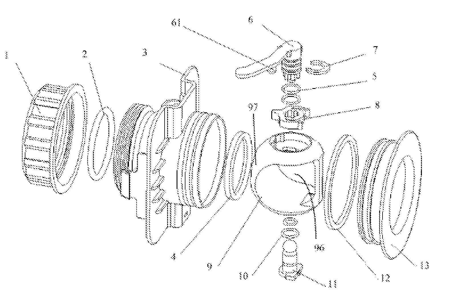
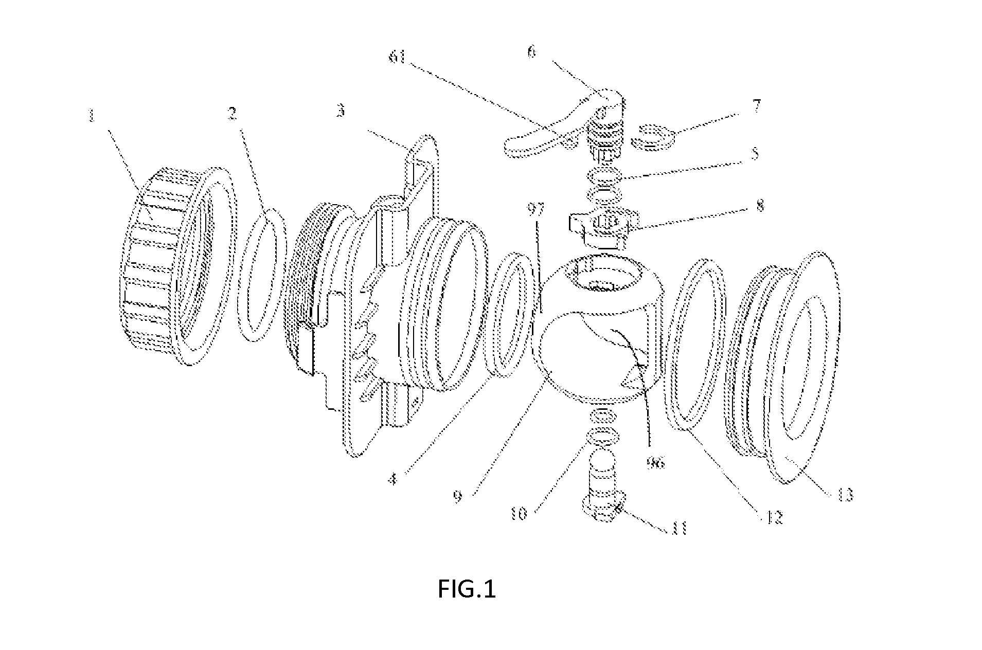
[0029]As shown in FIG. 1 and FIG. 2, the ball valve comprises a valve cover 1, a sealing ring 2, a valve body 3, a valve seat 4, an O-ring seals 5, a handle or valve rod 6, clip 7, a transmission member 8, a spherical valve cartridge 9, an O-ring seals 10...


PUM


Abstract

A valve cartridge assembly comprises a valve cartridge (9) and a transmission device. A recess (90) is formed on the top of the valve cartridge. The transmission device is provided in the recess (90) of the valve cartridge. A first transmission relationship and a second transmission relationship are formed between the transmission device and the recess (90) of the valve cartridge. The first transmission relationship is established so that the transmission device drives the valve cartridge (9) to rotate axially. When the movement in the first transmission relationship is ended, the relationship between the transmission device and the valve cartridge (9) switches from the first transmission relationship to the second transmission relationship. The second transmission relationship is established so that the transmission device drives the valve cartridge (9) to carry out a squeeze movement, and the squeeze movement enables the valve cartridge to have a moving component at least in an axial direction. The valve cartridge assembly is simple in structure and can provide an opening and closing operation with a low torque. And also disclosed is a valve with the above-mentioned valve cartridge assembly.

Description

FIELD OF INVENTION[0001]The invention relates to a valve and valve cartridge assembly thereof.BACKGROUND OF THE INVENTION[0002]In order to optimize the nominal diameter, pressure, torque, life, and other technical parameters of the ball valve, in recent years, there are a wide variety of valve complex opening and closing mechanisms.[0003]Chinese patent No. 200720082066 has disclosed a low-torque ball valve, which provides a low torque valve comprising a valve body, a valve ball, a valve seat, a bearing seat, a valve rod, a driving device, and a valve ball bearing connection. The patent has several disadvantages. The structure of the driving device is complex, and extremely occupies the external space of the valve body. The driving device involves many parts, resulting in the complexity of the assembling process. The rotation angle for opening or closing the valve is 180 degrees. The working space formed by the valve rod and the driving device requires a very high quality of sealing ...

Claims


Application Information

Patent Timeline
Patent Type & Authority Applications(United States)
IPC IPC(8): F16K5/20
CPCF16K5/204F16K5/0647F16K5/20
Inventor QIAN, ZUOCHENGYUAN, FANGTHORNHILL, MARTINLUTZU, GINO
Owner CHEP UK LTD
Learn More