
Computed tomography method, computer program, computing device and computed tomography system

a computed tomography and computed tomography technology, applied in image analysis, healthcare informatics, medical data management, etc., can solve problems such as poor quality of reconstructed volume data regions, and achieve the effects of reducing the influence of artefacts, reducing reconstruction time, and improving volume data quality

Active Publication Date: 2013-06-27
GE SENSING & INSPECTION TECH GMBH
View PDF6 Cites 1 Cited by
  • Summary
  • Abstract
  • Description
  • Claims
  • Application Information

AI Technical Summary

Benefits of technology

The present invention provides a computed tomography method that reduces reconstruction time and improves the quality of volume data. By individually evaluating each voxel in the data and tailoring the volume to be updated based on its quality, the influence of artefacts can be reduced. The evaluation step is performed in each iteration of the update process, and a update mask is generated to simplify the evaluation process. Overall, this method helps to improve the quality of computed tomography and reduce the time it takes to reconstruct images.

Problems solved by technology

Beyond this general demand, in many cases there exists the problem that certain regions of a given object cannot be scanned completely, or penetrated sufficiently, by x-rays during data acquisition, leading to regions of poor quality in the reconstructed volume data.

Method used


Image

  • Computed tomography method, computer program, computing device and computed tomography system
  • Computed tomography method, computer program, computing device and computed tomography system
  • Computed tomography method, computer program, computing device and computed tomography system

Examples


Embodiment Construction

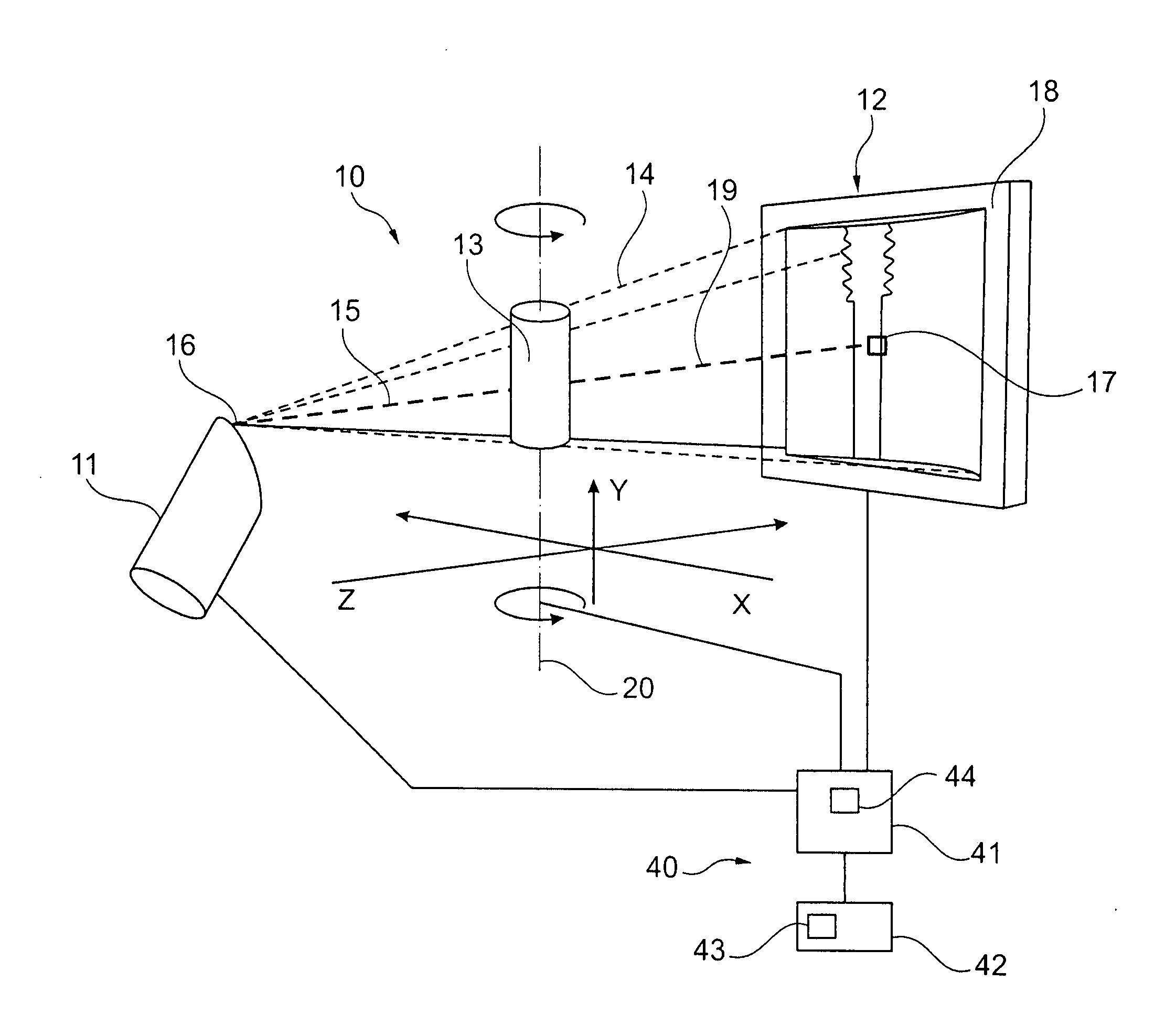
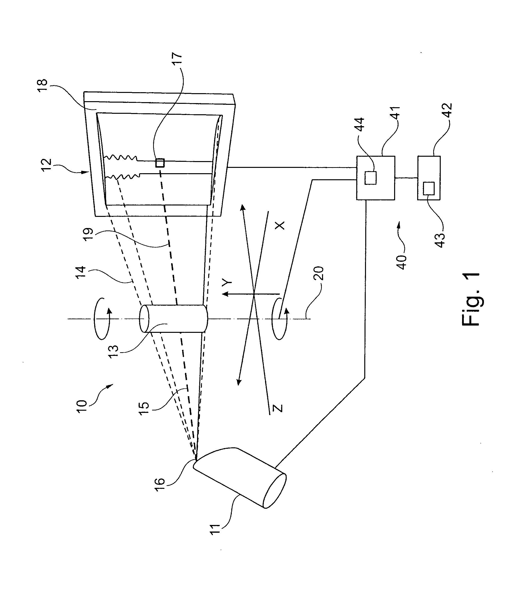
[0018]The computed tomography system shown in FIG. 1 comprises an x-ray system 10 arranged to take a set of x-ray projections of a sample 13. Therefore, the x-ray system 10 comprises an x-ray source 11, in particular an x-ray tube, emitting an x-ray cone 14, an imaging device 12, in particular an x-ray detector, and a sample manipulator 20 which is adapted to rotate the sample 13 around a vertical axis. The x-ray detector 12 in the present example is a two-dimensional detector, however it is also conceivable to use a one-dimensional detector. A set of x-ray projections of the sample 13 are taken by step-wise rotating the manipulator around a predetermined small angular step and taking an x-ray projection at every rotation angle. The rotation is carried out over the full 360° if the dimensions of the sample allow this. However, in case of large objects, for example large electronic boards, the sample can be rotated only about a certain angular range less than 360°, and accordingly an...


PUM


Abstract

A computed tomography method for determining a volumetric representation of a sample comprising reconstruction initial volume data of the sample from x-ray projections of the sample taken by an x-ray system, determining a part of the reconstructed initial volume data to be updated, and executing an iterative update process for generating configured to generate, using an iterative reconstruction method, updated volume data only for the part of the volume data determined to be updated. Determining the part of the sample volume to be updated comprises individually evaluating every single voxel in the reconstructed initial volume data, based on available quality information for the reconstructed initial volume data, whether or not the voxel fulfils a predetermined condition indicating that an update is required for the voxel, and the iterative update process generates the updated volume data only for the voxels which have been determined that an update is required.

Description

CROSS REFERENCE TO RELATED APPLICATIONS[0001]This is a national stage application under 35 U.S.C. 371(c) prior-filed, co-pending PCT patent application serial number PCT / EP2010 / 004191, filed on Jul. 9, 2010, the entire contents of which are incorporated herein by reference.BACKGROUND OF THE INVENTION[0002]Embodiments of the present invention relate to a computed tomography method, a computer program, a computing device and computed tomography system for determining a volumetric representation of a sample.[0003]It is a general demand in computed tomography to reduce the influence of artefacts, to reduce the reconstruction time and to improve the quality of the reconstructed volume data.[0004]Beyond this general demand, in many cases there exists the problem that certain regions of a given object cannot be scanned completely, or penetrated sufficiently, by x-rays during data acquisition, leading to regions of poor quality in the reconstructed volume data. Such cases relate for exampl...

Claims


Application Information

Patent Timeline
Patent Type & Authority Applications(United States)
IPC IPC(8): G06T7/00G16H30/40
CPCG06T7/0012G06F19/321G16H30/40
Inventor NEUSER, EBERHARDSUPPES, ALEXANDERROTHE, NILSHOTTER, MICHAELFROST, ANJA
Owner GE SENSING & INSPECTION TECH GMBH
Learn More