Atmospheric corrosion test procedure and its apparatus

a technology of atmospheric corrosion and test procedures, applied in measurement devices, scientific instruments, instruments, etc., can solve the problems of not satisfactorily reproducing the corrosion caused, requiring a long time, and a large difference in the size of sea salt particles flying in the natural environment, so as to improve the test accuracy and the effect of variation in the quantity of salt conten

Inactive Publication Date: 2013-06-27
HITACHI LTD
View PDF22 Cites 27 Cited by
  • Summary
  • Abstract
  • Description
  • Claims
  • Application Information

AI Technical Summary

Benefits of technology

[0010]According to the present invention, the corrosion caused due to the deposition of sea salt particles coming flying in the natural environment may be reproduced and a variance in quantity of the salt content deposited on the surfaces of the test pieces may be also reduced in the atmospheric corrosion test involving the repeated salt deposition step, achieving the improved test accuracy.

Problems solved by technology

However, when the salt mist is sprayed on the test pieces, the droplets of the sprayed salt mist, which is deposited and agglomerated on the test pieces, wet the surfaces thereof, leading to a considerable difference in size from the sea salt particle coming flying in the natural environment (about dozens of μm).
Thus, the above-mentioned salt spray procedure, in which saltwater is simply sprayed on the test pieces to deposit the salt particles on the surface thereof, has a problem to be solved that it can not satisfactorily reproduce corrosion caused due to the deposition of salt particles coming flying in the natural environment.
As disclosed in Japanese Patent No. 3834630, the salt deposition step, in which air bubbles are generated in sea water, is suitable for the test conducted in such a manner that corrosion is accelerated while salt particles are being deposited at a low speed; however, it causes a problem in the test conducted in such a manner that a dry-wet cyclic step of cycling between the dry state and the wet state is separated from a salt deposited step as disclosed in Japanese Patent No. 4218280,in that the salt deposition step requires long time, during which corrosion is excessively accelerated.
Furthermore, both the procedures according to the prior art disclosed in Japanese Patent No. 4218280 and Japanese Patent No. 3834630 have such a problem that when the salt deposition step is repeated, the quantity of the salt content deposited on the test pieces vary among the individual salt deposition steps, causing deteriorated reproducibility in the corrosion test.

Method used


Image

  • Atmospheric corrosion test procedure and its apparatus
  • Atmospheric corrosion test procedure and its apparatus
  • Atmospheric corrosion test procedure and its apparatus

Examples


first embodiment

[0038]FIG. 7 is a block diagram of an atmospheric corrosion test apparatus, which automatically carries out a series of steps of an atmospheric corrosion test procedure.

[0039]The atmospheric corrosion test apparatus 1 is composed of a thermo-humidistat chamber 110, a pump 115, a salt-water tank 120 (salt-water reservoir), a salt-water nozzle 125 (salt mist supplying unit), an exhaust unit 130, a rinsing water tank 140, a rinsing water nozzle 145, and a warm-air drying unit 150. Inside the thermo-humidistat chamber 110, a space is left for placing the test pieces 160. This figure shows the thermo-humidistat chamber 110 with the test piece 160 placed therein. The thermo-humidistat chamber 110 further has the salt-water nozzle 125, the rinsing water nozzle 145, and a warm-air drying unit 150 therein.

[0040]The thermo-humidistat chamber 110 also has a programming function capable of controlling independently the temperature and relative humidity therein and continuously varying among mor...

second embodiment

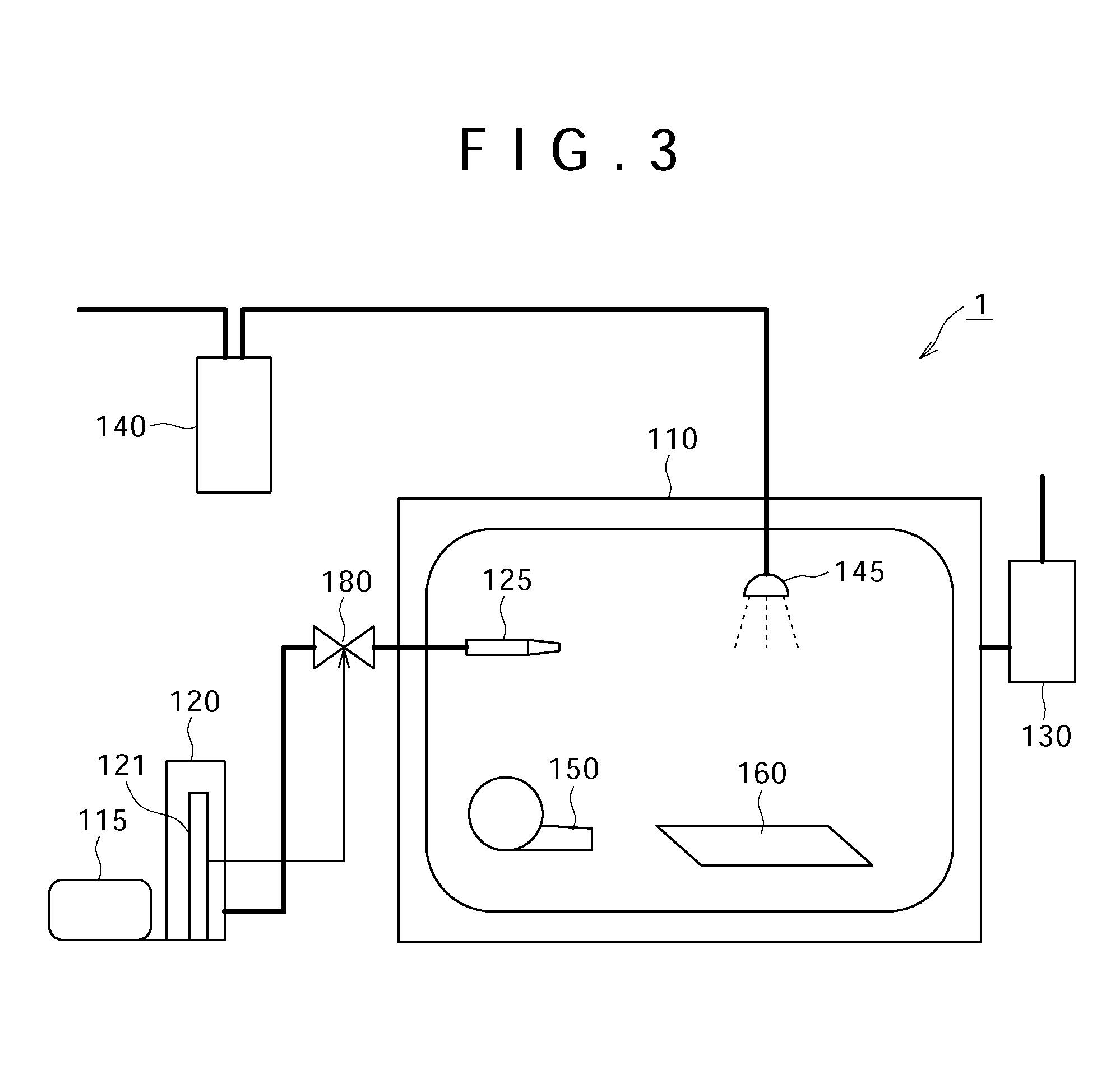
[0059]FIG. 9 is a block diagram of a semi-automatic apparatus carrying out the atmospheric corrosion test procedure, in which only the rinsing step is carried out manually and other steps are carried out automatically.

[0060]The atmospheric corrosion test apparatus 1 is composed of the thermo-humidistat chamber 110, the pump 115, the salt water tank 120 (salt water reservoir), the salt-water nozzle 125 (salt mist supplying unit), and the exhaust unit 130. The atmospheric corrosion test apparatus according to the second embodiment is different from the apparatus according to the first embodiment in that it does not include the rinsing water tank 140, the rinsing water nozzle 145, and the warm-air drying unit 150.

[0061]In this embodiment, an aluminum alloy sheet formed into the shape 70×70×3 mm was used for the test pieces 160.

[0062]Next, the atmospheric corrosion test procedure according to this embodiment will be described with reference to FIG. 8. The explanation described in the fi...

third embodiment

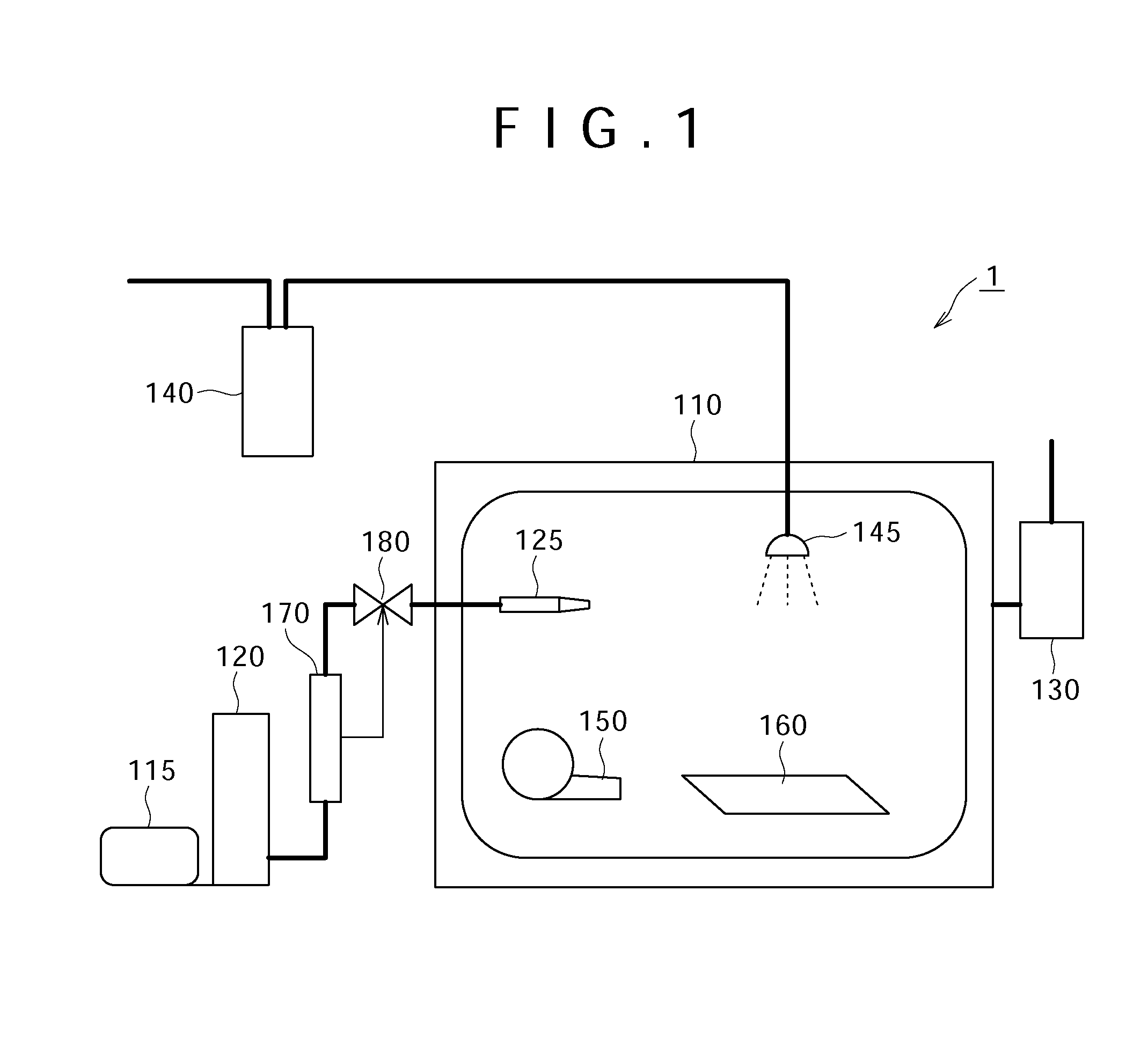
[0076]FIG. 1 is a block diagram of an apparatus automatically carrying out a series of steps of the atmospheric corrosion test procedure.

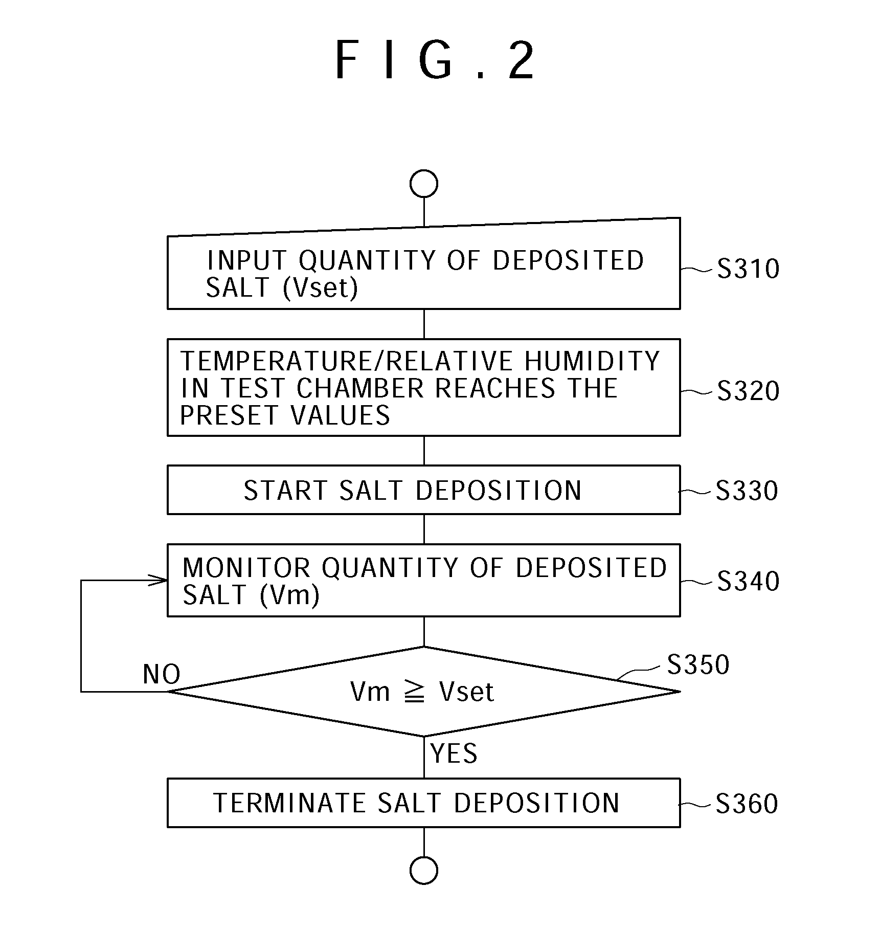
[0077]As known from this figure, the quantity (volume) of the salt mist supplied from the salt-water nozzle 125 is measured using an integrating flowmeter 170 (flow rate measuring unit) and closing an on-off valve 180 when the volume reaches a preset value to stop the spray of salt water. A rinsing water tank 140 and a warm-air drying unit 150 have been incorporated inside the thermo-humidistat chamber 110. This figure shows the apparatus according to this embodiment with test pieces 160 placed therein.

[0078]The explanation described in the first embodiment will be partially omitted and thereinafter, differences of the apparatus according to the third embodiment from the apparatus according to the first embodiment will be mainly described.

[0079]As with the first embodiment, the thermo-humidistat chamber 110 according to this embodiment is capable o...


PUM

PropertyMeasurementUnit
temperatureaaaaaaaaaa
RH±3aaaaaaaaaa

Abstract

Provided are an atmospheric corrosion test procedure and an apparatus used for the test. The procedure involves a salt spray step for supplying salt content containing chloride ions on the surfaces of test pieces placed in a thermo-humidistat chamber and a subsequent dry-wet cyclic step including a dry sub-step for drying the surface of the test pieces in the thermo-humidistat chamber at a low relative humidity and a subsequent wet sub-step at a higher relative humidity than that in the dry sub-step, which are cycled. The salt content is supplied by spraying the salt water in the salt spray step. An exhaust step for removing the salt mist sprayed inside thermo-humidistat chamber is further inserted between the salt deposition step and the dry sub-step. The quantity of the salt content deposited on the surfaces of the test pieces is controlled by adjusting the quantity of the sprayed salt water.

Description

FIELD OF THE INVENTION[0001]The present invention relates to an atmospheric corrosion test procedure for metallic materials and its apparatus.BACKGROUND OF THE INVENTION[0002]A salt spray test defined in JIS Z 2371 and a cyclic corrosion test defined in JIS K 5600-7-9 have been known for the tests for evaluating the corrosion resistance of metallic materials used in the atmosphere.[0003]Japanese Patent No. 4218280 also discloses a corrosion test procedure carried out in the simulated corrosion environment, to which test pieces are actually exposed, by adjusting the test conditions, such as the quantity of salt content to be deposited on the test pieces, and the temperature and relative humidity. The corrosion test procedure disclosed in Japanese Patent No. 4218280 involves a step of depositing a given quantity of salt content on the test pieces and a subsequent dry-wet cyclic step, in which a dry state and a wet state are cycled in preset temperature and relative humidity conditions...

Claims


Application Information

Patent Timeline
Patent Type & Authority Applications(United States)
IPC IPC(8): G01N17/00
CPCG01N17/006
Inventor FUJII, KAZUMITAKAHASHI, KATSUHITO
Owner HITACHI LTD
Why Eureka
Try Eureka