
Impedance responsive ablation RF driving for moderating return electrode temperature

a technology of responsive ablation and driving force, applied in the direction of medical science, surgical instrument details, surgery, etc., can solve the problems of attendant discomfort and, potentially, injury, and achieve the effect of reducing the likelihood of return electrode overheating

Inactive Publication Date: 2013-06-27
ACESSA HEALTH INC
View PDF3 Cites 5 Cited by
  • Summary
  • Abstract
  • Description
  • Claims
  • Application Information

AI Technical Summary

Benefits of technology

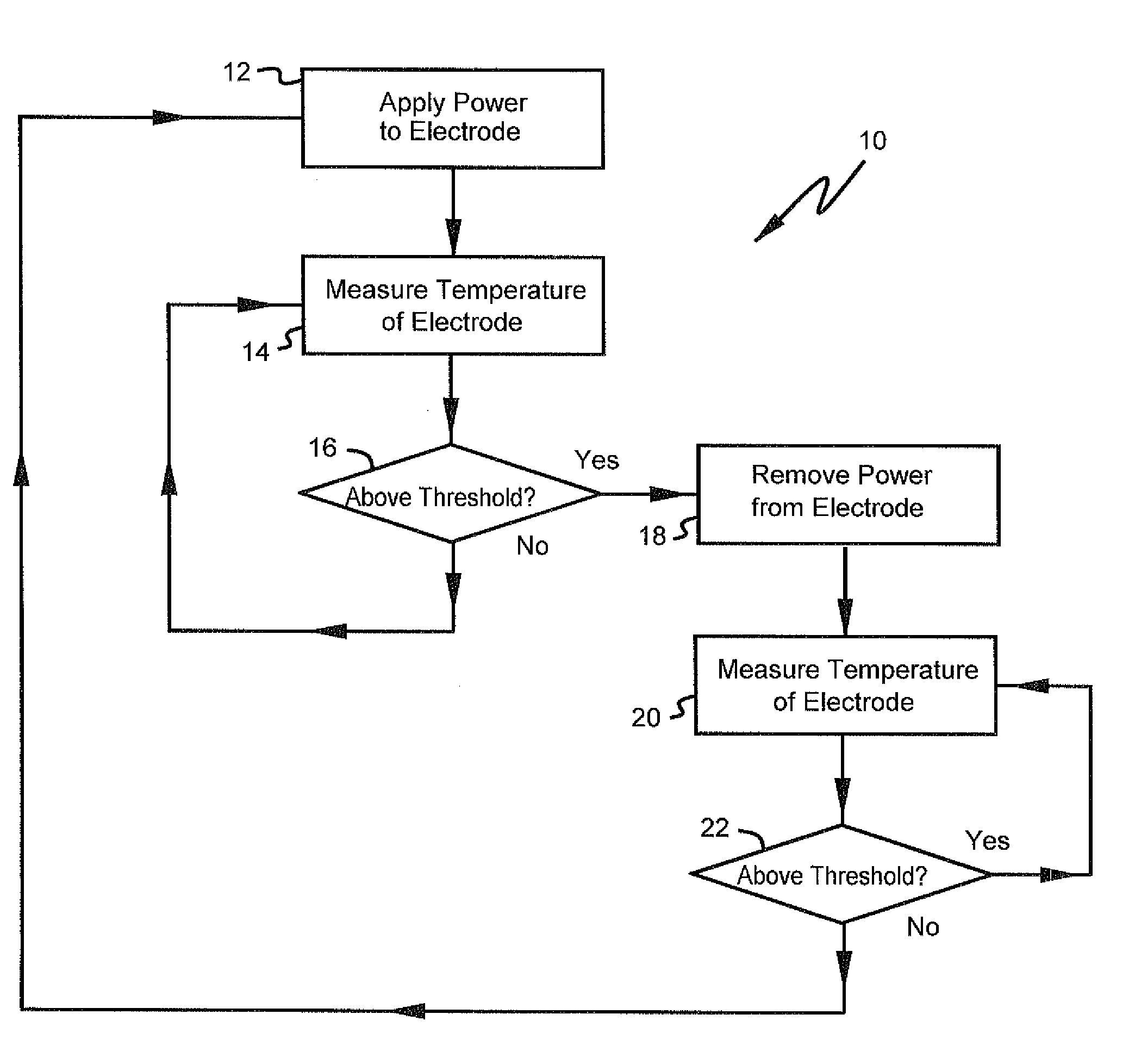
[0004]In accordance with the invention, an apparatus and method are provided to reduce the likelihood of return electrode overheating. Generally, in accordance with the invention, the same is achieved by monitoring electrode temperature and varying either the electrodes which are being driven with radio frequency ablation energy, and / or varying the amount of radio frequency ablation energy being coupled to the electrodes.
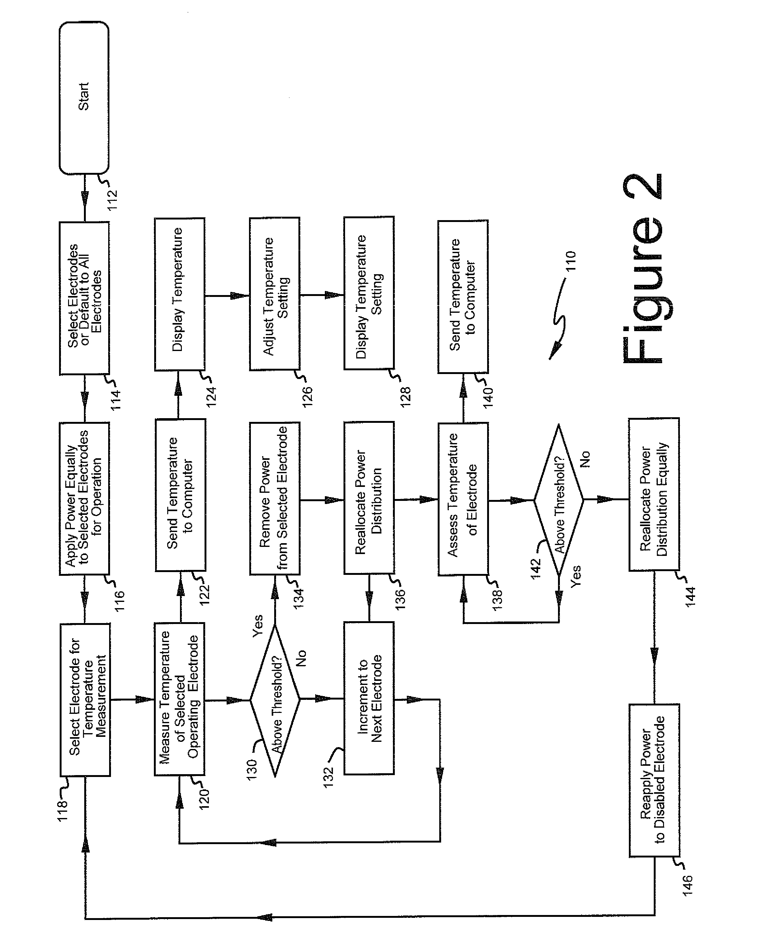
[0005]In accordance with the invention, it is recognized that RF current flow is concentrated at the leading edge of the pad (the cephalic edge of the pad in the case of uterine fibroid ablation). Hence, temperature rises in the tissue proximate the leading edge. In accordance with the invention, there may be a plurality of pads with single or multiple electrodes on a single substrate. Each electrode is thus associated with a zone of skin positioned underneath it switching between electrode which overlie different zones may be referred to as zone switching. Zone switching is done to essentially create a new leading edge as the old one warms up. Pad zone switching is intended to distribute the heating that occurs on the skin under a return electrode by changing the zone that is being used. The majority of the heating occurs along the leading edge of a return electrode because the path from that edge to the ablation site is shortest and thus has the lowest impedance. By, in effect, moving that leading edge around, local heating is reduced, minimizing the probability of a burn.
[0006]In a typical arrangement return electrode pads having one or more electrodes are located on both of the patient's legs. If each leg has a single return electrode pad divided into two or three electrically isolated electrodes and corresponding zones, in accordance with the invention the zones may be oriented across the leg, like stripes. If at one point in time the first (e.g. cephalic) zone is in use as the return electrode, heating occurs primarily on the leading edge of that zone. A short time later (e.g. ten seconds) the system can switch to another electrode associate with a different zone. That moves the localized heating to the leading edge of the new zone and gives the body time to cool the previously-used zone. Blood flow and conduction will tend to bring the skin under the “old” leading edge back to normal body temperature. In effect, we are moving the return electrode from one place to another and are avoiding prolonged heating of a single patch of skin.
[0009]As an alternative to using the coolest zone or other selection strategy, the system may be designed to periodically change zones, for example every thirty seconds to always implement a switch in active pad to act as a fail safe for a pad that happens to lift right where a sensing thermocouple is placed. The thermocouples are preferably placed at the cephalic midline of the zone to make it less likely that it will peel up there, but if it did and there is not enough of a change in impedance to trigger a contact quality alarm threshold, by moving the active zone every set number of seconds, a risk of injury is mitigated.

Problems solved by technology

A potential complication during the deployment and use of such devices is overheating in the area surrounding the return electrodes, with attendant discomfort and, potentially, injury.

Method used


Image

  • Impedance responsive ablation RF driving for moderating return electrode temperature
  • Impedance responsive ablation RF driving for moderating return electrode temperature
  • Impedance responsive ablation RF driving for moderating return electrode temperature

Examples


Embodiment Construction

[0040]Typically, ablation is performed using a device comprising an elongated handle which may be gripped by the surgeon. Extending from the handle is a thin elongated, often pointed sometimes stiff but somewhat flexible catheter which may be used to puncture the skin and enter the region where the particular growth or lesion to be removed is located.

[0041]The above device is of particular value with respect to the ablation of uterine fibroids. Alternatively, a device with a rounded tip may be used to implement ablation in parts of the body that allow entrance without piercing, for example the urethra. Other areas of application include liver lesions, prostate cancer, and so forth. The present invention applies to all of the above and similar devices.

[0042]In such devices a plurality of stylets extends from the pointed tip and may be deployed into a growth to be removed. For example, the tip, under the guidance of ultrasound imaging may be advanced into a liver lesion. Stylets exten...


PUM


Abstract

The inventive method for ablating a tissue mass associated with a human or animal patient being treated comprises positioning an ablating electrode in a tissue mass to be ablated. A plurality of return electrodes are positioned on the patient. Electrical energy is applied between the return electrodes and the ablating electrode. The temperature of the return electrodes is measured to generate a temperature measurement signal which is used to control ablation current through the return electrodes.

Description

TECHNICAL FIELD[0001]The invention relates to methods and apparatus for preventing return electrodes in a radio frequency ablation system (such as a uterine fibroid ablation system) from overheating and causing injury or discomfort to the patient.BACKGROUND OF THE INVENTION[0002]There are a number of applications in which radio frequency ablation is a preferred procedure. Such applications include the treatment of various growths and lesions, such as prostate cancer, liver cancer, and uterine fibroids.[0003]Such techniques generally involve the application of power between a return electrode and an ablation device, such as a pointed trocar tip with a plurality of extendable ablation stylets. A potential complication during the deployment and use of such devices is overheating in the area surrounding the return electrodes, with attendant discomfort and, potentially, injury.SUMMARY OF THE INVENTION[0004]In accordance with the invention, an apparatus and method are provided to reduce t...

Claims


Application Information

Patent Timeline
Patent Type & Authority Applications(United States)
IPC IPC(8): A61B18/18
CPCA61B18/1233A61B18/18A61B18/16A61B2017/00084A61B2017/3413A61B2018/00577A61B2018/00678A61B2018/00702A61B2018/00708A61B2018/00726A61B2018/00791A61B2018/00875A61B2018/162A61B2018/165A61B18/1482
Inventor EPSTEIN, GORDON
Owner ACESSA HEALTH INC
Learn More