Method and device for controlling an internal combustion engine
- Summary
- Abstract
- Description
- Claims
- Application Information
AI Technical Summary
Benefits of technology
Problems solved by technology
Method used
Image
Examples
Embodiment Construction
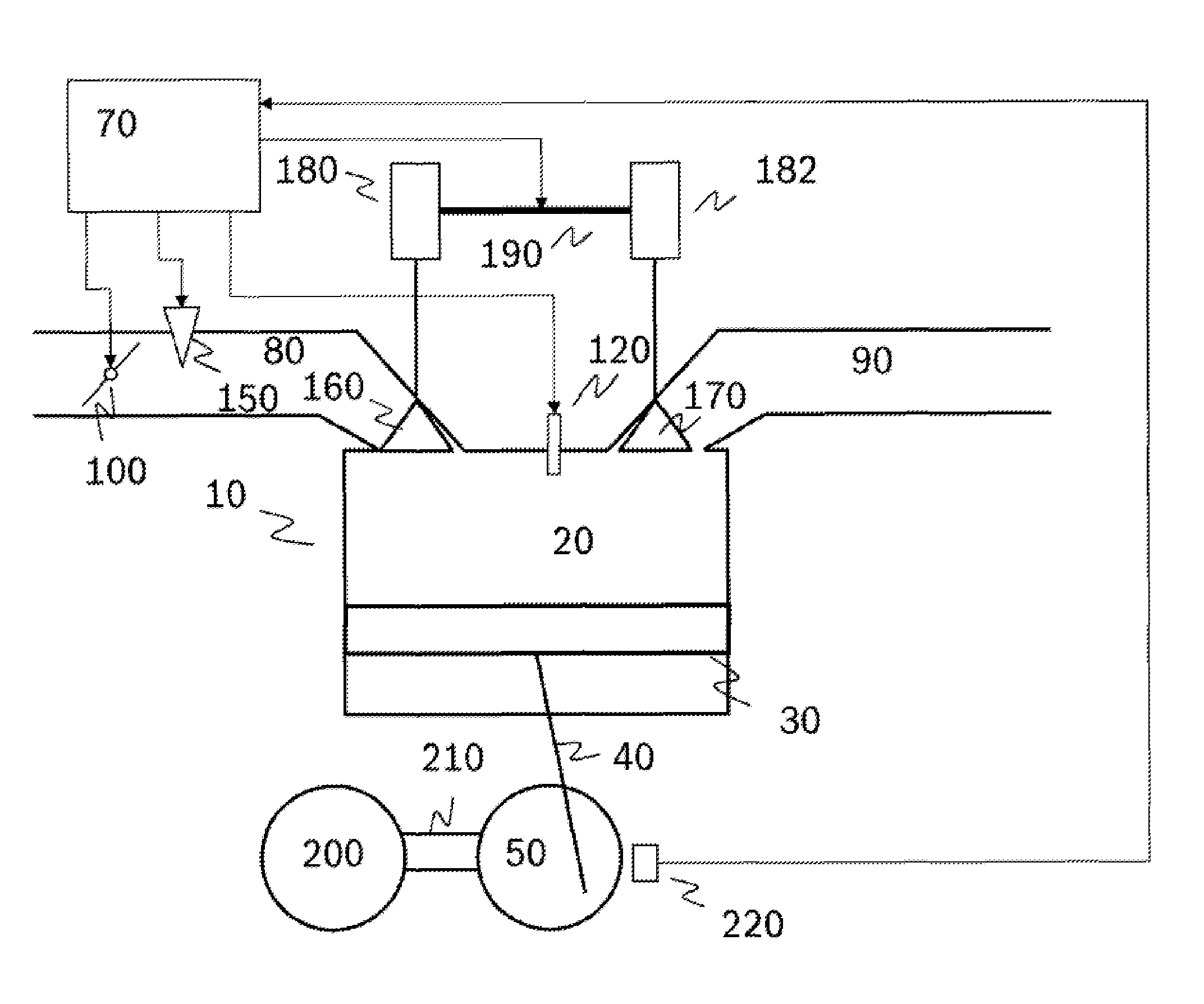
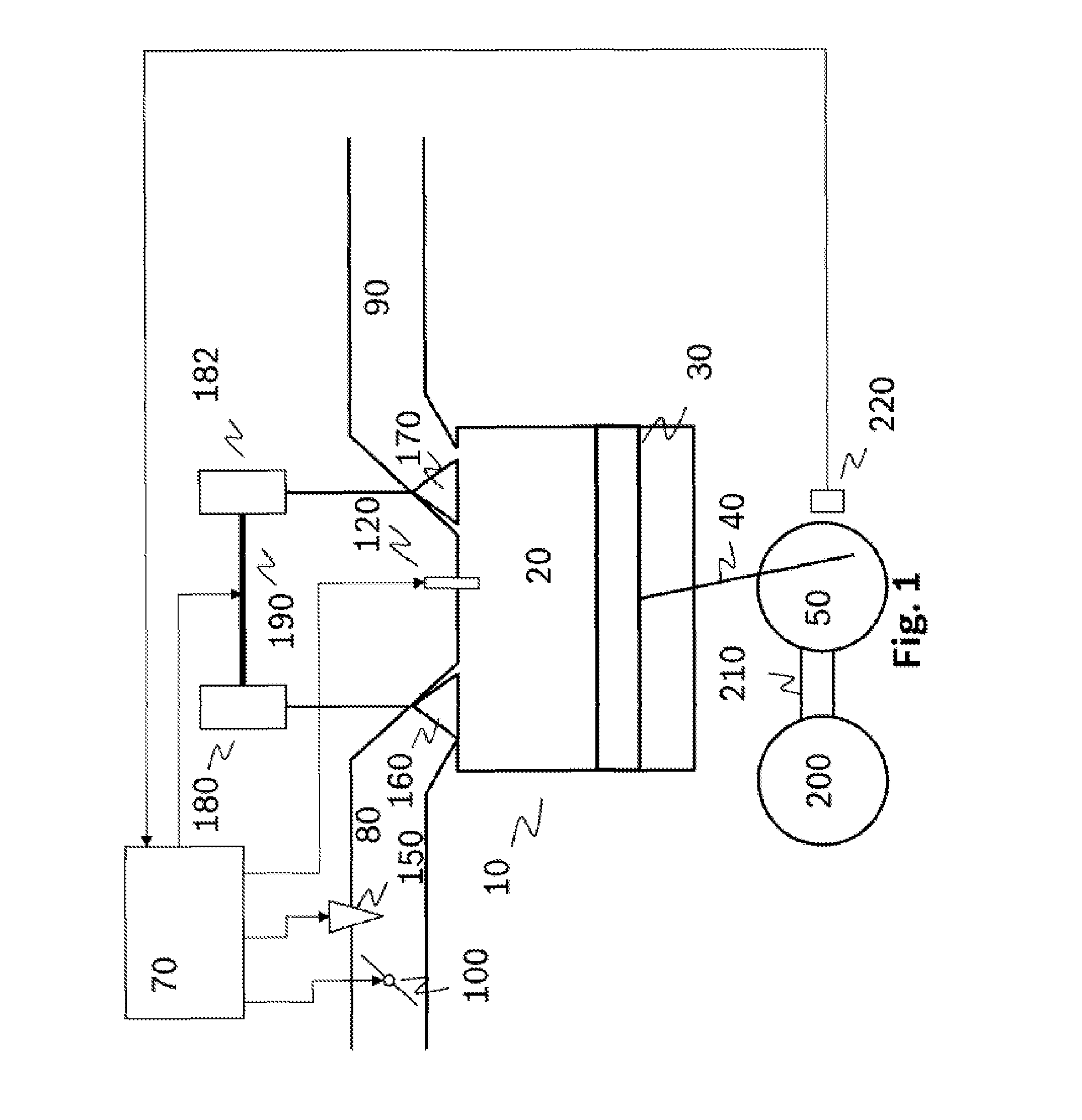
[0028]FIG. 1 shows a cylinder 10 of an internal combustion engine having a combustion chamber 20, a piston 30, which is connected by a connecting rod 40 to a crankshaft 50. The piston 30 performs an up and down motion in a known manner. The reversal points of the motion are referred to as dead center positions. The transition from an upward motion to a downward motion is referred to as the top dead center position, while the transition from a downward motion to an upward motion is referred to as the bottom dead center position. An angular position of the crankshaft 50, referred to as a crank angle, is conventionally defined relative to the top dead center position. A crankshaft sensor 220 detects the angular position of the crankshaft 50.
[0029]Air to be combusted is sucked into the combustion chamber 20 via an intake pipe 80 in a known manner during a downward motion of the piston 30. This is referred to as the intake stroke or inlet stroke. The combusted air is forced out of the co...
PUM
 Abstract
Description
Claims
Application Information
 - R&D
- Intellectual Property
- Life Sciences
- Materials
- Tech Scout
- Unparalleled Data Quality
- Higher Quality Content
- 60% Fewer Hallucinations
Browse by: Latest US Patents, China's latest patents, Technical Efficacy Thesaurus, Application Domain, Technology Topic, Popular Technical Reports.
© 2025 PatSnap. All rights reserved.Legal|Privacy policy|Modern Slavery Act Transparency Statement|Sitemap|About US| Contact US: help@patsnap.com


